Atlas EC
A conductivity meter to measure electrolytes in a liquid!
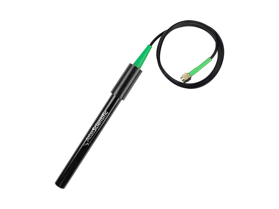
Image Credit: Atlas Scientific
Working principle
To measure electrical conductivity, we'll use a sensor called a conductivity meter. In the case of Smart Citizen, using Atlas Scientific sensors, the conductivity sensor does not have an integrated temperature sensor, so we will need to use an additional temperature sensor to measure the temperature at which we are taking our sample. This temperature sensor should be submerged at the same time when we take conductivity measurements.
If there is an active temperature sensor taking simultaneous readings, the reported values from the conductivity meter will be based on the measured temperature, and this process will be automatic. If you do not have a temperature sensor, the reading will based on a temperature of 25ºC, which may represent a source of error. Additionally, it is important to check corrections for extreme pH values (greater than 12 or less than 2), as these can introduce large errors in the results on Smart Citizen (and Atlas Scientific) sensors.
Usage and considerations
How to prepare the sensor
Before and after measuring, the sensor should be cleaned with deionized water. In case of debris, it can be cleaned with laboratory tissue to avoid dust. If it is very dirty or contains oily residues, it can also be cleaned first with a little detergent and then with distilled water.
Calibration
If the sensor is not calibrated, follow the procedure described below.
Calibration
Warning
When calibrating don't use the normal read sensor command, this command applies temperature/salinity compensation, calibration should be done without any compensation. Instead you should use control sensorName com,r and that will return the raw metrics that sensor can provide. On the documentation of each sensor calibration procedure we describe the format of this metrics.
You need to perform a 3 step calibration with a dry point and a 2-point calibration with the calibration solutions.
Datasheet
Here you can find the datasheet:
- Calibration info on page 12
- Calibration commands on page 55
Example commands
control conductivity com,r
control conductivity com,K,[probeType]
control conductivity com,K,?
control conductivity com,cal,[dry,clear,84]
control conductivity com,cal,low,1413
control conductivity com,cal,high,12,880
control conductivity com,cal,?
2-point calibration
This is the order of the calibration:
- set probe type
- dry point
- two-point calibration
Set probe type
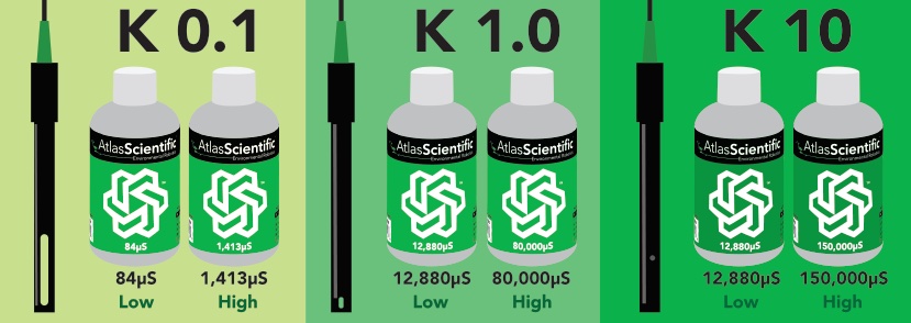
Depending on which probe you have (check drawing for reference) you should set the probe type to K 0.1, 1.0 or 10 (new drivers have K1.0 as default):
To set the correct probe type:
control conductivity com,K,1.0
and check which type is set:
control conductivity com,K,?
?K,1.0
About the sensor
The Electrical Conductivity sensor provides four different metrics:
- Electrical Conductivity → EC
- Total Dissolved Solids → TDS
- Salinity → S
- Specific Gravity → SG
The data is presented in order and comma separated EC,TDS,S,SG, for instance 0.00,0,0.00,1.000
Readings are 0?
It is normal that if the probe type has been changed (for instance, you are using a K10 probe), that the readings are 0 after setting the probe type.
Dry calibration
Follow the steps below with the dry sensor before introducing it to the calibration solutions. You need to do this step even if the readings in dry state are 0.
-
Read the sensor multiple times until the reading is stable:
control conductivity com,r 0.00,0,0.00,1.000 control conductivity com,r 0.00,0,0.00,1.000 ... -
Issue the dry calibration command:
control conductivity com,cal,dry
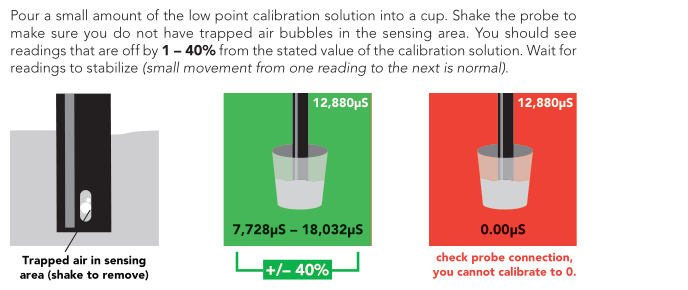
Low point calibration
You can check the recommended calibration solutions for each probe on the Probetypes drawing (for instance, for K1.0 probe, 12,880uS and 80,000uS are recomended)
-
Read the sensor multiple times until the reading is stable:
control conductivity com,r 13470,7278,7.76,1.0 control conductivity com,r 13230,7144,7.61,1.0 ... -
Issue the low point calibration command. The value to input is the one of the calibration solution, for example 128800:
control conductivity com,cal,low,12880
After this command readings will not change.
High point calibration
Repeat this steps with high point calibration solution and when the readings stabilize issue the command. Again, remember that the value to input here is the one from the calibration solution, for instance 80000:
control conductivity com,cal,high,80000
After this steps the two point calibration is complete and the readings will change.
How to measure
If you aren't familiar with the site where you are taking samples, measure at several points at different depths and sections. In case there is little water movement, take several samples at different depths.
- Take the measurement at the desired depth, letting the sensor stabilize for at least 60 seconds. To find out if it is stabilized, wait for variations of ±5 μS/cm for measurements ≤100 μS/cm or ±3% for measurements >100 μS/cm. Do not immerse the probe too deeply, ensuring it does not reach sediment areas.
- Takes temperature and conductivity measurements, without moving the water probes (take both at the same time).
- When finished, clean the probe with deionized water.
Warning
The conductivity sensor needs to be immersed to cover the active element:

It also prevents bubbles from accumulating in the sensor covering. Simply shake the sensor a little to remove the bubbles:

Factory reset procedure
Why is this needed?
You may need to do a factory reset for water sensors for different reasons. However, the most common case is a wrong calibration process and it's very much related to a wrongful automatic temperature compensation of the sensor while calibrating the sensor.
To explain further: EC, DO and pH sensor readings are automatically compensated by temperature readings. If there is an existing temperature correction in the EZO driver, or there is a correction in the middle of the calibration process, the data available for the calibration process will be invalid. Follow the steps below to be make sure there is no correction while you calibrate the probes.
Each EZO driver has it's independent calibration and status. This process needs to be done per driver (i.e. per EZO metric). To make a factory reset procedure for the EZO drivers follow the steps below:
-
Make sure that the Smart Citizen Data board will not take any readings while you follow the calibration process. The best option is to reset the configuration to the defaults. Make sure you back-up your information before:
- The config command will output your current configuration. Copy it and keep it safe:
config- Then issue the default configuration:
config -defaults- The LED should be red now (the Data Board is in Setup mode)
-
Issue the factory reset command to the driver in question. For instance, for the conductivity one:
control cond com factory 0 -
Now you can check what the status of the device is:
control cond com cal,? ?CAL,0 -
Reset the kit
-
Follow the calibration process as you would normally would.
-
Reconfigure the kit using the
configcommand, by putting back the information you backed-up before:config -mode ...
Danger
After finishing the calibration process restart your SCK to start from a clean state.
Resources
Additional resources
On the importance of salinity for physical oceanography, as well as its application to the identification of fronts between different bodies of water:
-
Ocean Science In Your Kitchen | Salinity & Density (Royal Museums Greenwich)
-
Ocean Science In Your Kitchen | Salinity & the Sea (Royal Museums Greenwich)
-
Ocean Science in Your Kitchen | Salinity & Temperature (Royal Museums Greenwich)
In case you want to delve deeper into conductivity measurements, you can review the references at USGS: Science for a Changing World: Specific Conductance.