Firmware features
Sensor auto-detection
Any supported sensor connected to the data board is autodetected and enabled if the configuration defaults to that. This means, that the firmware can be configure to autodetect a series of supported sensors, and that each sensor can be enabled or disabled, both by default, or by shell configuration.
Below, you can see an example of sensor auto-detection:
Detecting: AlphaDelta 1A... found, Enabling AlphaDelta 1A
Detecting: AlphaDelta 1W... found, already enabled!!!
Detecting: AlphaDelta 2A... found, already enabled!!!
Detecting: AlphaDelta 2W... found, already enabled!!!
Detecting: AlphaDelta 3A... found, already enabled!!!
Detecting: AlphaDelta 3W... found, already enabled!!!
Detecting: AlphaDelta Temperature... found, already enabled!!!
Detecting: AlphaDelta Humidity... found, already enabled!!!
Detecting: Grove ADC... nothing!
Detecting: INA219 Bus voltage... nothing!
Detecting: INA219 Shunt voltage... nothing!
Detecting: INA219 Current... nothing!
Detecting: INA219 Load voltage... nothing!
Detecting: DS18B20 Water temperature... nothing!
Detecting: Atlas PH... nothing!
Detecting: Atlas Conductivity... nothing!
Detecting: Atlas Specific gravity... nothing!
Detecting: Atlas Dissolved Oxygen... nothing!
Detecting: Atlas DO Saturation... nothing!
Detecting: Grove OLED... nothing!
Configuration via Shell
The board firmware is fully customizable without requiring any changes to the core software. That includes enabling or disabling sensors, the sampling frequency of the sensors or the operation mode, among many other settings. There different configuration options via the Shell are available when the board is connected over USB.
Info
Have a look at the guide for different platforms here.
Flash storage
The Smart Citizen Kit (from 2.1 onwards) readings are stored in an onboard flash memory buffer before being published. If the SCK RTC clock is in sync, the SCK will start taking readings and saving them in the flash memory. If an SD-card is available, it will also save them there and, if the Wi-Fi credentials and platform token are configured, the data will be published to the network via MQTT. In other words, we will always have a backup for the readings taken during the last ~70 days in the flash memory.
Hold your horses
The rest of this section is very technical, and it's meant to document how the implementation was done for anyone willing to reuse it.
Hardware
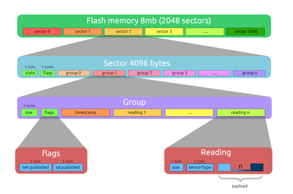
The memory chip that we use (S25FL064L), it's an 8 MB SPI flash nonvolatile memory. To manage it, we use the SPI Memory Arduino library. The minimum erasable unit is a 4kb sector, the full memory contains 2,048 sectors with a total of 8,388,608 bytes or 8 MB.
A normal reading group with the default urban board is composed of 11 readings. That means that we expect each reading to take 7 bytes: an average of 5 bytes for the reading itself plus 2 overhead bytes for the type of sensor and the reading size. Each group should have a total of 77 bytes of readings, 2 bytes of size, 2 bytes of flags and 4 bytes of the time stamp. That means we can expect a normal group to be around 85 bytes. This means we can store almost 100,000 groups of readings, or around 70 days of readings with standard sensor hardware. This number can vary a little, though.
About flash memory lifespan, rounding numbers we can say we have enough space to store 2 months (60 days) of readings, according to the Flash memory datasheet we have at least 100,000 erase cycles: 2 months per cycle means 200,000 months, so we can expect more than 16k years!.
Data organization
Flash sectors
The minimum erasable unit is a sector (4 KB), so we use this as a base for data organization. On the first 3 bytes of each sector we store information about its contents, in this way we can find which ones are empty, currently in use or have valid data.
enum SectorAddr {
    SECTOR_STATE = 0x00,
    SECTOR_NET   = 0x01,
    SECTOR_SD    = 0x02
};
The first byte of each sector (SECTOR_STATE) describes if the sector is empty or already used. On boot, we scan sector by sector until we find an empty one to store new data.
The SECTOR_NET and SECTOR_SD bytes of each sector contain the flags related to the publish state of contained data. This bytes are only marked if all the groups of the sector are already published and the sector is full.
When all flash sectors are marked as used we will erase the oldest data sector and reuse it.
Data groups
Readings are grouped by the time there were taken and saved sequentially inside flash memory sectors. On the beginning of each group, we store information about it.
enum GroupAddr {
    GROUP_SIZE =        0x00,
    GROUP_NET  =        0x02,
    GROUP_SD   =        0x03,
    GROUP_TIME =        0x04,
    GROUP_READINGS =    0x08
};
In the GROUP_SIZE bytes, we store the size in bytes of the full group with all its contents. This allows us to start reading the sector starting on the first group and jump from group to group very fast.
The GROUP_NET and GROUP_SD bytes of each group contain the flags related to the publishing state of contained data, as default they are in NOT_PUBLISHED state until we set them to PUBLISHED.
The time and date of when these readings were taken is stored in the GROUP_TIME bytes in Epoch time format.
Starting on the GROUP_READINGS byte, we store the sensor readings data (256 max). The first byte of each reading contains its full size in bytes, the second byte the sensor identifier (SensorType) and starting on the third byte the sensor data is stored in ASCII chars.
Sizes
A normal reading group with the default urban board hardware installed is composed by 11 readings, we expect each reading to take 7 bytes: an average of 5 bytes for the reading itself plus 2 overhead bytes for SensorType and size, so each group should have a total of 77 bytes of readings, 2 bytes of size, 2 bytes of flags and 4 bytes of the time stamp. That means we can expect a normal group to be around 85 bytes.
Info
We have 8 MB (8,388,608 bytes) of flash memory that means storing almost 100,000 groups of readings or around 70 days of readings with standard sensor hardware. This number can vary a little, because we will lose some space at the end of each sector.
About flash memory lifespan, rounding numbers we can say we have enough space to store 2 months (60 days) of readings, according to the Flash memory datasheet we have at least 100,000 erase cycles: 2 months per cycle means 200,000 months that's more than 16k years!!.
User interface
Some aspects of the flash memory can be managed by the user via the SCK shell interface, issuing the help command you can see a brief description of the flash command interface:
flash: Shows and manage flash memory state [no-param -> info] [-format (be carefull)] [-dump sect-num (0-2040)] [-sector sect-num] [-recover sect-num/all net/sd]
Without any parameter, the flash command will scan the memory and print out a table of its contents, showing totals at the end. Be patient, scanning can take a long time if your flash has data. Below there is a summary of each option:
-format: will erase the full flash memory.-dump: will dump (in hexadecimal values) the content of the requested sector.-sector: will show general information about the data contained on the requested sector.-recover: takes 2 parameters: the sector number or the keyword all and one keyword to indicate how to recover the data (net or sd)