TI INA219
A digital sensor for measuring electric current and voltage!
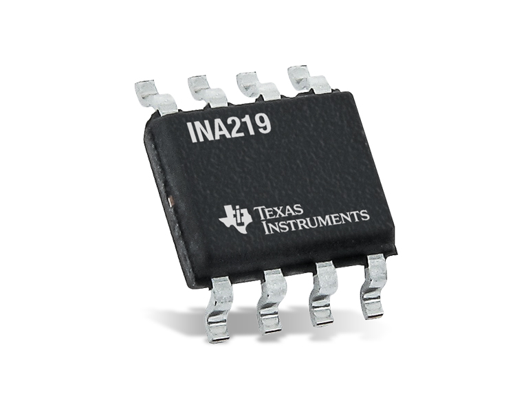
Image Credit: Texas Instruments
Experimental support
The INA219 is not enabled in any of the default firmware builds. To use it, you need to compile the firmware with the SCK_WITH_INA219 flag. Check the guide on enabling additional features.
Working principle
The INA219 is a current and voltage monitor by Texas Instruments, with a digital (I2C) interface 1. It measures current by placing a small resistor, called shunt, in series with the circuit to monitor: the current flowing through the shunt produces a small voltage drop across it, proportional to the current (Ohm's law). The INA219 measures this voltage drop, and also the voltage of the circuit (the bus voltage), and calculates the current and power.
The INA219 is a high-side monitor: the shunt is placed between the power supply and the load, on the positive side of the circuit. This allows to measure the current without interrupting the ground of the circuit.
It can be used, for instance, to measure the power consumption of a device, the current produced by a small solar panel, or the voltage of a battery.
Usage and considerations
The easiest way to use the INA219 is with a breakout board, such as the Adafruit INA219 breakout, which includes a 0.1Ω shunt resistor. Connect it to the Auxiliary connector on the data board with 4-wire grove to female header cables, or with a STEMMA QT to Grove cable for the newer versions of the board.
I2C address
The firmware looks for the INA219 on the I2C address 0x41. Most breakouts use 0x40 by default, so you need to change the address of the board. In the Adafruit breakout, this is done by bridging the A0 solder jumper.
The circuit to monitor is connected to the VIN+ and VIN- terminals of the breakout: VIN+ to the power supply, and VIN- to the load. When enabled, the following metrics are available:
| Metric | Shell name | Units | Description | API |
|---|---|---|---|---|
| Bus voltage | INA219 Bus voltage |
V | Voltage between VIN- and ground |
- |
| Shunt voltage | INA219 Shunt voltage |
mV | Voltage drop across the shunt | - |
| Current | INA219 Current |
mA | Current through the shunt | - |
| Load voltage | INA219 Load voltage |
V | Bus voltage plus shunt voltage (voltage of the power supply) | - |
Metrics with - in the API column are not published to the platform.
You can check the readings with the read and monitor commands, for instance:
read ina219 current
The firmware configures the sensor for a range of up to 32V and 1A (with the 0.1Ω shunt of the Adafruit breakout).
Maximum voltage
The INA219 can only measure bus voltages up to 26V. Higher voltages can damage the sensor and the SCK. Also make sure that the ground of the monitored circuit is connected to the ground of the SCK, otherwise the bus voltage readings will not be valid.
Performance
| Property | Value |
|---|---|
| Sensor type | High-side current and voltage monitor with digital interface (I2C) |
| Bus voltage range | 0 – 26 V |
| Current range (SCK) | Up to 1 A (with a 0.1Ω shunt) |
| ADC | 12 bits |
Resources
References
-
Texas Instruments. “INA219 Zerø-Drift, Bidirectional Current/Power Monitor With I2C Interface - Datasheet.” https://www.ti.com/product/INA219. ↩