TI ADS1115
A high precision 16-bit, 4 channel ADC, used in the Analog Sensor Board.
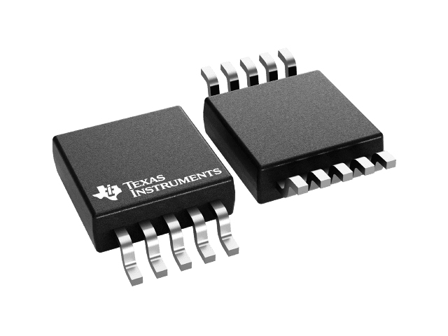
Image Credit: Texas Instruments
Analog Sensor Board
The ADS1115 is the ADC used in the Analog Sensor Board, which is the recommended way to connect analog sensors to the SCK, such as the Alphasense electrochemical sensors. Check the board's page for the hardware details, and this page for how the ADC works and how the firmware reads it.
Working principle
The ADS1115 is an analog to digital converter (ADC) by Texas Instruments 1. Many sensors do not have a digital interface, and instead provide an analog output: a voltage that changes with the measured magnitude. An ADC measures this voltage and converts it into a number that the SCK can read via I2C.
The ADS1115 has a 16-bit resolution (it divides its measurement range in 65536 steps), and includes a programmable gain amplifier (PGA). The PGA allows to change the measurement range, so that small voltages can be measured with a much better resolution. It has four inputs, which can be used as four single-ended channels (measured against ground), or as two differential channels.
The ADS1015 is a version of the same chip with a lower resolution (12 bits) and a higher sampling rate.
Usage and considerations
The ADS1X15 is enabled in all the default air firmware builds (SCK2.1 onwards). The ADC can be connected to the Auxiliary connector through the Analog Sensor Board, or with a breakout board such as the Adafruit ADS1115 breakout.
Each ADS1115 can be configured on one of four I2C addresses (0x48, 0x49, 0x4A or 0x4B), so up to four ADCs (16 channels) can be used at the same time. The Analog Sensor Board has two ADS1115 on board, with selectable addresses. The firmware detects each ADC on boot, and creates one metric per channel:
| Address | Shell names | Units | API |
|---|---|---|---|
0x48 |
ADS1x15 ADC 0x48 Ch0 to ADS1x15 ADC 0x48 Ch3 |
V | 133, 134, 135, 136 |
0x49 |
ADS1x15 ADC 0x49 Ch0 to ADS1x15 ADC 0x49 Ch3 |
V | 138, 139, 140, 141 |
0x4A |
ADS1x15 ADC 0x4A Ch0 to ADS1x15 ADC 0x4A Ch3 |
V | 143, 144, 145, 146 |
0x4B |
ADS1x15 ADC 0x4B Ch0 to ADS1x15 ADC 0x4B Ch3 |
V | 148, 149, 150, 151 |
You can check the readings with the read and monitor commands, for instance:
read ads1x15 adc 0x48 ch0
ADC values interpretation
All channels are read as single-ended inputs (voltage against ground), and the result is reported in volts. To get the best resolution for every reading, the firmware selects the gain automatically:
- It first reads the channel with the widest range (±6.144V)
- Depending on the value, it selects the smallest range that fits the reading (±4.096V, ±2.048V, ±1.024V, ±0.512V or ±0.256V)
- It reads the channel again with this gain, and converts the result into volts
With the smallest range, the resolution is below 10 µV, which is useful for sensors with very small signals.
Input voltage
Even if the widest range is ±6.144V, the voltage at the inputs should never be higher than the supply voltage of the ADC (3.3V by default in the SCK), or lower than ground. Higher voltages can damage the ADC. Note that the Analog Sensor Board can be configured to work up to 5.5V.
The firmware reports the raw voltage of each channel. Converting this voltage into the measured magnitude (a gas concentration, for instance) depends on the sensor, and is done in post-processing.
Ground values
Voltage levels directly connected to GND, read as +12V in the ADC due to an overflow internal to the TI ADS chip, only on the ADS1115 version.
Performance
| Property | Value |
|---|---|
| Converter type | Delta-sigma ADC with programmable gain amplifier and digital interface (I2C) |
| Resolution | 16 bits |
| Channels | 4 single-ended (as used in the SCK) or 2 differential |
| Input ranges (SCK) | From ±0.256V to ±6.144V (automatic) |
| I2C addresses | 0x48, 0x49, 0x4A, 0x4B |
Resources
References
-
Texas Instruments. “ADS111x Ultra-Small, Low-Power, I2C-Compatible, 860-SPS, 16-Bit ADCs - Datasheet.” https://www.ti.com/product/ADS1115. ↩