Firmware
The firmware is OOP and is entirely written in C++. Both processors the core ARM MCU and the ESP8266 WIFI are developed as part of the same framework integrating seemingly by using a set of bridge libraries that provide a unifies the RPC architecture.
A note about versions
The first version of the software was initially developed for the Making Sense project under European Community’s H2020 Programme under Grant Agreement No. 688620.
The current version has been funded by the iSCAPE project project under European Community’s H2020 Programme under Grant Agreement No. 689954.

Firmware updates are done via the micro USB port using the Platform IO software available for Linux, Mac and Windows.
Architecture
Core Microcontroller
| Name | Functions |
|---|---|
| Pins | Definition for the MCU pinout |
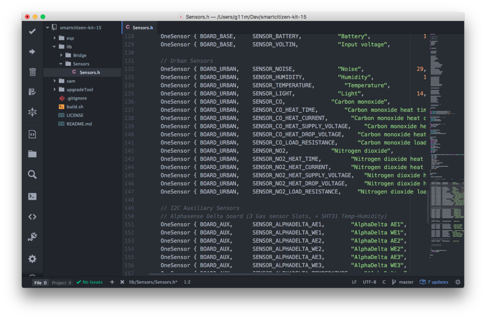
| Sensors | Definition for all the supported sensors |
| SckBase | Manages the core operations: power, connectivity, peripherials |
| SckAux | Manages the sensors connected on the AUX connector |
| SckList | Manages internal Flash memory data storage |
| SckUrban | Manages the sensors on the Urban Sensor Board |
| SckBatt | Manages the battery charging process |
| SckButton | Manages users button interaction actions |
| SckLed | Manages light status for user feedback |
| Commands | Library to absracts the core features on to a simple shell interface |
Dependencies
- SPIMemory Library
- RTCZero Library
- SdFat Library
- Arduino Json Library
- Adafruit INA219 Library
- U8g2 Library
- RadioHead Library
- FlashStorage Library
- Dallas Temperature Library
- Sparkfun CCS811 Library
- Sparkfun MediaTek I2C Interface Library
- Sparkfun u-blox Arduino GNSS Library
- TinyGPSPlus Library
- LinkedList Library
- Adafruit ADS1015 Library
- ArduinoZero PMUX Report Library
- MCP342X Analog-to-Digital Converter Library
- DS2482 Library
- Adafruit MPL3115A2 Library
- I2C Soil Moisture Sensor Library
- SmartSmart Citizen Kit Gases Pro Board Library
- Sparkfun ToF Range Finder - VL6180 Arduino Library
- Adafruit BME680 Library
- Adafruit Unified Sensor Driver Library
- Sparkfun SCD30 CO₂ Sensor Library Library
WiFi Module
| Name | Functions |
|---|---|
| SckESP | Runs all the Wi-Fi networking related functions |
Dependencies
- Time Library
- ArduinoJson Library
- RemoteDebug Library
- RadioHead Library
- PubSubclient Library
- ESPAsyncWebServer Library
Shared
| Name | Functions |
|---|---|
| Config | Provides a shared configuration between the two MCUs |
Data management
The board is capable of storing the recorded data offline on its internal dedicated flash memory of 8MB and later publish this over Wi-Fi connectivity provided by an Espressif ESP8266. Data is published using MQTT messages to the Smart Citizen Platform. NTP is used for syncing the built-in RTC. For long term offline storage, the board provides a standard microSD socket where card in the orders of GB can be employed. That ensures extended periods of data in the order of decades can be stored.
Configuration
The board firmware is fully customizable without requiring any changes to the core software. That includes enabling or disabling sensors, the sampling frequency of the sensors or the operation mode. There different configuration options via the Serial Shell available when the board is connected over USB.
Detecting: AlphaDelta 1A... found, Enabling AlphaDelta 1A
Detecting: AlphaDelta 1W... found, already enabled!!!
Detecting: AlphaDelta 2A... found, already enabled!!!
Detecting: AlphaDelta 2W... found, already enabled!!!
Detecting: AlphaDelta 3A... found, already enabled!!!
Detecting: AlphaDelta 3W... found, already enabled!!!
Detecting: AlphaDelta Temperature... found, already enabled!!!
Detecting: AlphaDelta Humidity... found, already enabled!!!
Detecting: Grove ADC... nothing!
Detecting: INA219 Bus voltage... nothing!
Detecting: INA219 Shunt voltage... nothing!
Detecting: INA219 Current... nothing!
Detecting: INA219 Load voltage... nothing!
Detecting: DS18B20 Water temperature... nothing!
Detecting: Atlas PH... nothing!
Detecting: Atlas Conductivity... nothing!
Detecting: Atlas Specific gravity... nothing!
Detecting: Atlas Dissolved Oxygen... nothing!
Detecting: Atlas DO Saturation... nothing!
Detecting: Grove OLED... nothing!
Shell
The firmware provides a comprehensive command shell over USB to manage all the kits functionalities for advanced users.
Use any Serial console as screen, platformio device monitor, or the serial monitor on the Arduino IDE
Info
Have a look at the guide for different platforms here
Storage
Readings files YY-MM-DD.CSV
These files are generated and updated by the kit in a daily manner. When a SD is detected the SCK will automatically save the sensors into it.
The SCK creates an additional CSV file once there is a hardware reset. A reset takes place every night at 3-4am with the purpose to avoid data loss because a software problem (i.e. blocked software). The SCK then stores the data in a file with a sequential name, and does so by changing the filename to YY-MM-DD.01, .02... depending on the amount of resets it sees during a certain day. The latest data is always in the file with .CSV extension. An example of a day with two resets (ad hoc and the programmed one):
YY-MM-DD.01 -> first reset
YY-MM-DD.02 -> second reset
YY-MM-DD.CSV -> latest file
The user can safely change the extension of these files back to .CSV and concatenate them:
YY-MM-DD.01 -> YY-MM-DD_01.CSV
YY-MM-DD.02 -> YY-MM-DD_02.CSV
YY-MM-DD.CSV -> YY-MM-DD.CSV
Warning
If there is a problem with the device, sometimes it can be that the SD card contains many files for a single day. These resets might go unnoticed, and the SD card files can be a way of detecting an issue.
Debug log file DEBUG.txt
The debug file is generated and updated by the kit, only if the debug mode is enabled on the configuration.
When the debug mode is enabled the verbosity level of this file is defined by the outlevel (normal, verbose or silent).