Electrochemical Sensors
Working principle
The electrochemical cells used are toxic gas sensors from Alphasense Ltd. that operate in an amperometric mode. That is, they generate a current that is linearly proportional to the fractional volume of the toxic gas in the environment:
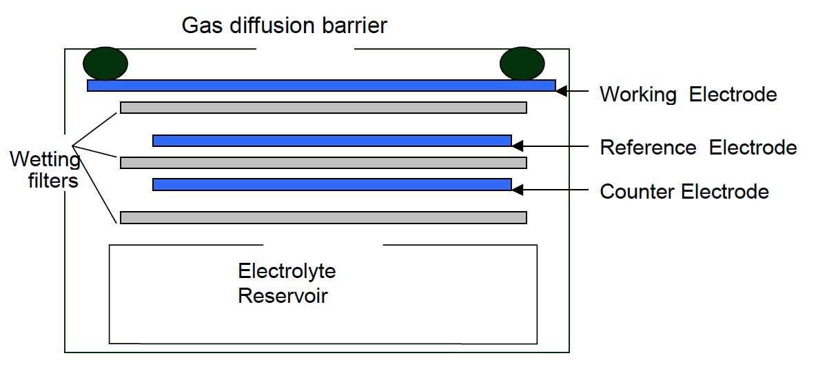
Image Source: Alphasense Ltd.
These electrochemical sensors are comprised of four electrodes:
- Working electrode
- Auxiliary electrode
- Counter electrode
- Reference electrode
The working electrode is where the oxidation (CO, H2S, NO, SO2) or reduction (NO2, Cl2) of the toxic gas to be measured takes place. This electrode is exposed to the outside air and directly exposed to all gases in the air including the gas to be measured. This electrode may as well be poisoned if it is exposed to certain gases that either adsorb onto the catalyst (such as acetylene onto CO sensors), or react, creating by-products which inhibit the catalyst (NO2 or aromatics onto H2S sensors).
The auxiliary electrode is an electrode of the same characteristics to those of the working electrode, but it is buried inside an electrolite and, hence, it is not in contact with the target gas. Since it is isolated from external conditions that could affect the working electrode, it serves as a reference to the measurements provided by the latter.
The counter electrode balances the reaction of the working electrode – if the working electrode oxidises the gas, then the counter electrode must reduce some other molecule to generate an equivalent current, in the opposite sense. For example, where carbon monoxide will be oxidised on the working electrode, oxygen will be reduced on the counter electrode.
The reference electrode anchors the working electrode potential to ensure that it is always working in the right conditions. It is important that the reference electrode has a stable potential, keeping the working electrode at the right electrochemical potential to maintain a constant sensitivity, good linearity and minimum sensitivity to interfering gases.
Therefore, while the sensor response is exposed to the target gas, it creates a current flowing from the working to the counter electrode or viceversa (depending on the oxidative or reductive nature of the target gas). This current has been found to be nicely responsive to target gas and therefore subject to characterisation and calibration.
Reduction vs Oxidation Electrochemical Sensor
As mentioned above, the counter electrode is meant to balance the reaction of the working electrode. This determines the current direction within the board: whether it goes from the working electrode to the counter electrode or viceversa.
-
Oxidation sensors, such as CO, provoke a positive current out of the working electrode and the larger the amount of CO present, the larger (positive) is this current.
-
Reduction sensors, such as NO2, provoke a negative current, i.e: going into the sensor and the larger the amount of NO2 present, the larger (negative) is this current
Usage and considerations
Alphasense Ltd. provides the calibration data in laboratory conditions for each of the electrochemical cells used. This data can be used to calculate pollutant concentration and to correct for known effects by temperature deviations.
Alphasense Ltd. provides very useful application notes for the sensor usage.
Pollutant calculation based on calibration data in laboratory conditions, can be insightful enough for certain applications, but it might not suffice for some conditions in which the sensors are exposed to other pollutants or in harsh environments. For this reason, two different approaches build on top of the laboratory calibration data:
- Usage of more advanced physical models as detailed in 1
- Usage of site-specific calibration models with short-term deployments in co-location with reference measurement equipment and generalised calibration models derived from the junction of these 4.
Stabilisation
The electrochemical sensors need stabilisation time under the testing conditions they will be at. It is important to set and power the sensors with sufficient time (1-2 days) on the test environment for them to adapt. The newer the sensor, the more stabilisation time it requires. For this deployment, you will be receiving brand new sensors.
Humidity and temperature extremes will require of further sensor adaptation, in order to dry out or absorb the necessary humidity for their proper functioning.
Danger
Do not extract/attach the sensor capsule from the base board while powered, this could irreversibly damage the sensor.
Open questions
These methods, however, are still open to discussion and more research is necessary to address all use cases. For this reason, the use of these sensors in the Smart Citizen Station is tailored to each use and adapted to the calibration needs of the deployment.
Characterisation techniques based on manufacturer data and physical models (i.e. classical linear regression using sensor sensitivity, span and zero) require a big development effort in order to characterise the sensor behaviour that, in the case of low-cost sensors, is affected by a wide variety of external factors such as temperature, humidity and pollutant cross-sensitivity, each of which imply a larger characterisation effort and that can’t be fully represented in a controlled setting. On the other hand, statistical models are able to generate models that describe the sensor behaviour in a mathematical way, but they need to be properly adjusted with large amounts of test data, preferably in the actual deployment site. This approach can be applied per sensor, or to a batch of sensors, assuming that the inter-sensor variation is low or that they can be normalised.
In the case of deploying the sensors in different locations, the conditions of these sites should be sufficiently similar to those when the model was generated, since many models won’t be able to extrapolate well, or account for effects they have not seen (i.e. temperature gradients, specific pollutants, etc). How much is sufficiently similar, depends on the type of model and it is not easy to determine and, since this is not often assessed easily, researchers suggest (5, 6) that a co-location prior to and post data acquisition with reference sensors should be carried out. In any case, the development of these models highly depends on the amount and quality of the data obtained from both: sensor data and reference data. In the case of reference data 6 have pointed out that reference stations can deviate up to 15% from the actual pollutant concentration, but this has not been taken into account in this study.
Since co-location possibilities could be limited, two options are compared for the calibration of these sensors: a specific on-site calibration with sensor co-location, aiming to calibrate the sensors with the data from that period; and a general model approach, in which all the co-location tests from the different sensors deployed are input into a statistical model that aims to describe the global behaviour. Whether these methods are able to generalise or not, it's yet to be answered, and it's probably to be defined for each use case in particular.
Results
A whole section of the electrochemical sensors validation is available in the iSCAPE D7.8 report on Sensor monitoring experiences and technological innovations 4.
-
The use of electrochemical sensors for monitoring urban air quality in low-cost, high-density networks - M.I. Mead, O.A.M. Popoola, G.B. Stewart, P. Landshoff, M. Calleja, M. Hayesb, J.J. Baldovi, M.W. McLeod, T.F. Hodgson, J. Dicks, A. Lewis J. Cohen, R. Baron, J.R. Saffell, R.L. Jones ↩
-
Development of a baseline-temperature correction methodology for electrochemical sensors and its implications for long-term stability - Olalekan A.M. Popoola*, Gregor B. Stewart, Mohammed I. Mead, Roderic L. Jones ↩
-
Modelling atmospheric composition in urban street canyons - Vivien Bright, William Bloss and Xiaoming Cai ↩
-
ISCAPE D7.8 Sensor monitoring experiences and technological innovations] ↩↩
-
Kizel et al - Node-to-node field calibration of wireless distributed air pollution sensor network. In: Environmental pollution (2017) ↩
-
Dušan et al - In search of an optimal in-field calibration method of low-cost gas sensors for ambient air pollutants: comparison of linear, multilinear and artificial neural network approaches. In: Atmospheric Environment (2018) ↩↩