Hardware
Inside the SCK
Main Board
The main board contains the basic functionality like sensor I/O to read de sensor values, communication with the platform through the wifi module, manage the power and battery charging.
PINOUT
The SCK Main Board connects to the Sensor Board 16 pin connector. This is how the pins are laid out on the board. The numbers in brackets are the actual pin numbers of the micro controller. Pins IO are digital and S are analogue.
| GND | GND |
| IO3 (10) | IO2 (9) |
| IO1 (13) | IO0 (5) |
| SCL | SDA |
| S5 (A1) | S4 (A0) |
| S3 (A3) | S2 (A2) |
| S1 (A5) | S0 (A4) |
| VBAT | VBAT |
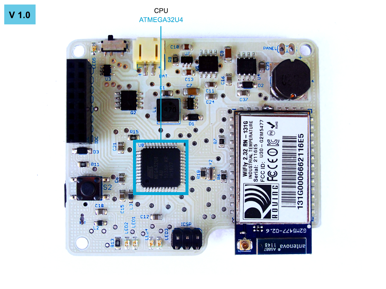
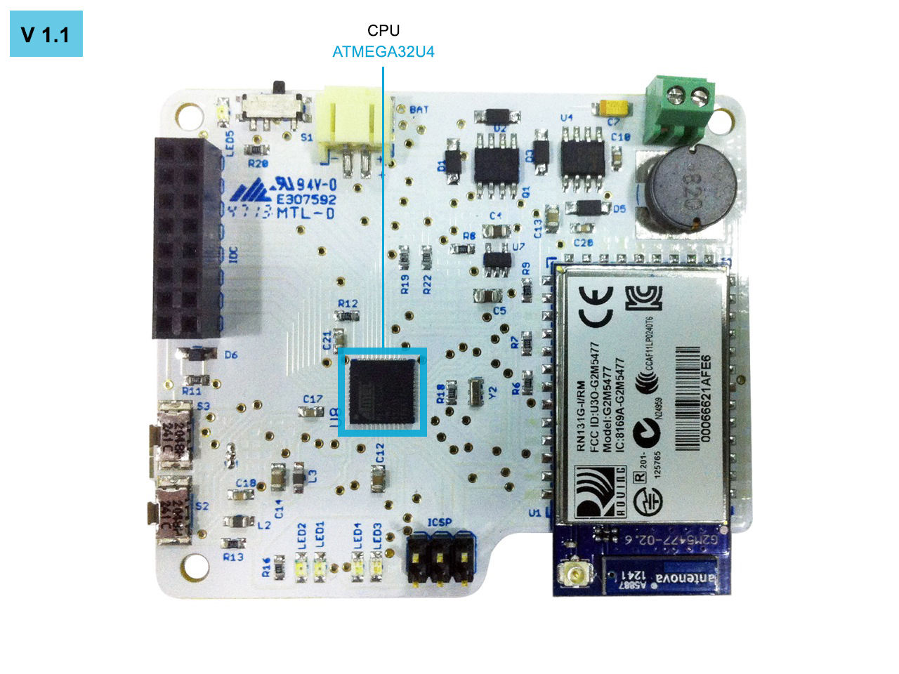
CPU
Both versions of the SCK (1.0 and 1.1) are using the same CPU, ATMEGA32U4 (Arduino Leonardo). With the difference that the 1.0 works at 5V and 16MHZ and the 1.1 works at 3.3V and 8MHZ. In the 1.1 version we’ve improved the power consumption.
This CPU has native USB and an UART TTL port allowing us to connect directly with the WIFI module.
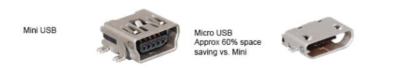
USB CONNECTOR
The 1.0 version uses a Mini USB connector and 1.1 version uses a Micro USB.
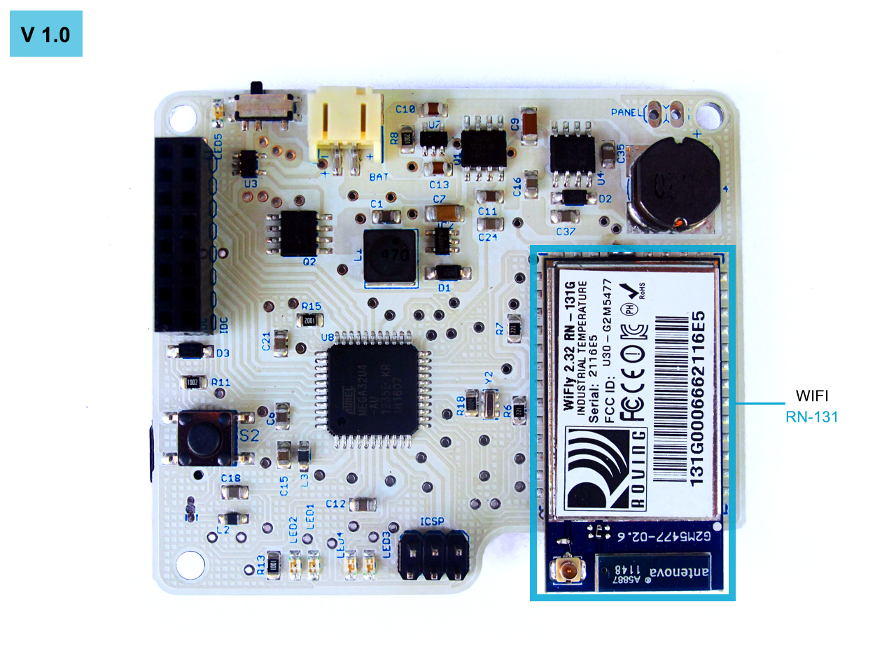
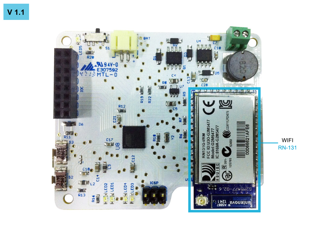
WIFI MODULE
The RN-131 module is a standalone, embedded wireless 802.11 b/g networking module. With its small form factor and extremely low power consumption, the RN-131 fits perfectly for the SCK wireless communication requirements.
Main features:
- Qualified 2.4-GHz IEEE 802.11b/g transceiver
- Ultra-low power: 4 uA sleep, 40 mA Rx, 210 mA Tx
- High throughput, 1 Mbps sustained data rate with TCP/IP and WPA2
- Small, compact surface-mount module
- On-board ceramic chip antenna and U.FL connector for external antenna
- 8-Mbit flash memory and 128-KB RAM
- UART hardware interface
- 10 general-purpose digital I/O pins
- 8 analog sensor interfaces
- Real-time clock for wakeup and time stamping
- Accepts 3.3-V regulated or 2 to 3 V battery
- Supports ad hoc and infrastructure networking modes
- On board ECOS -OS, TCP/IP stacks
- Wi-Fi Alliance certified for WPA2-PSK
- FCC/CE/ICS certified and RoHS compliant.
- Industrial (RN-131G) and commercial (RN-131C) grade temperature options
WIFLY module - RN-131 datasheet
BATTERY POWERING
For powering the SCK, in both versions, we are using a 3.7v 2000 mAh li-on battery.
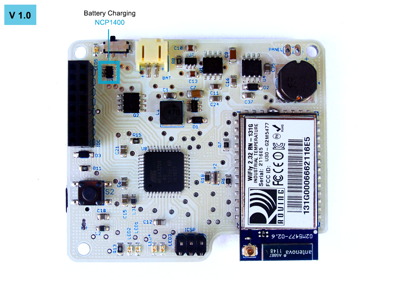
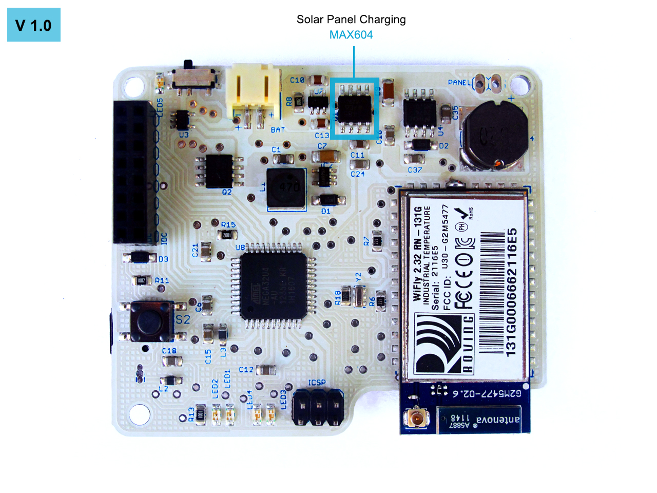
SCK version 1.0 uses two different voltages, 3.3V and 5V to power the IC’s. To get 5V from 3.3v we are using a step-up based on NCP1400, thus having a stable voltage at 5v and 100mA. On the other hand, to regulate the voltage and to obtain 3.3v, the SCK uses the IC MAX604.
NCP1400 datasheet MAX604 datasheet
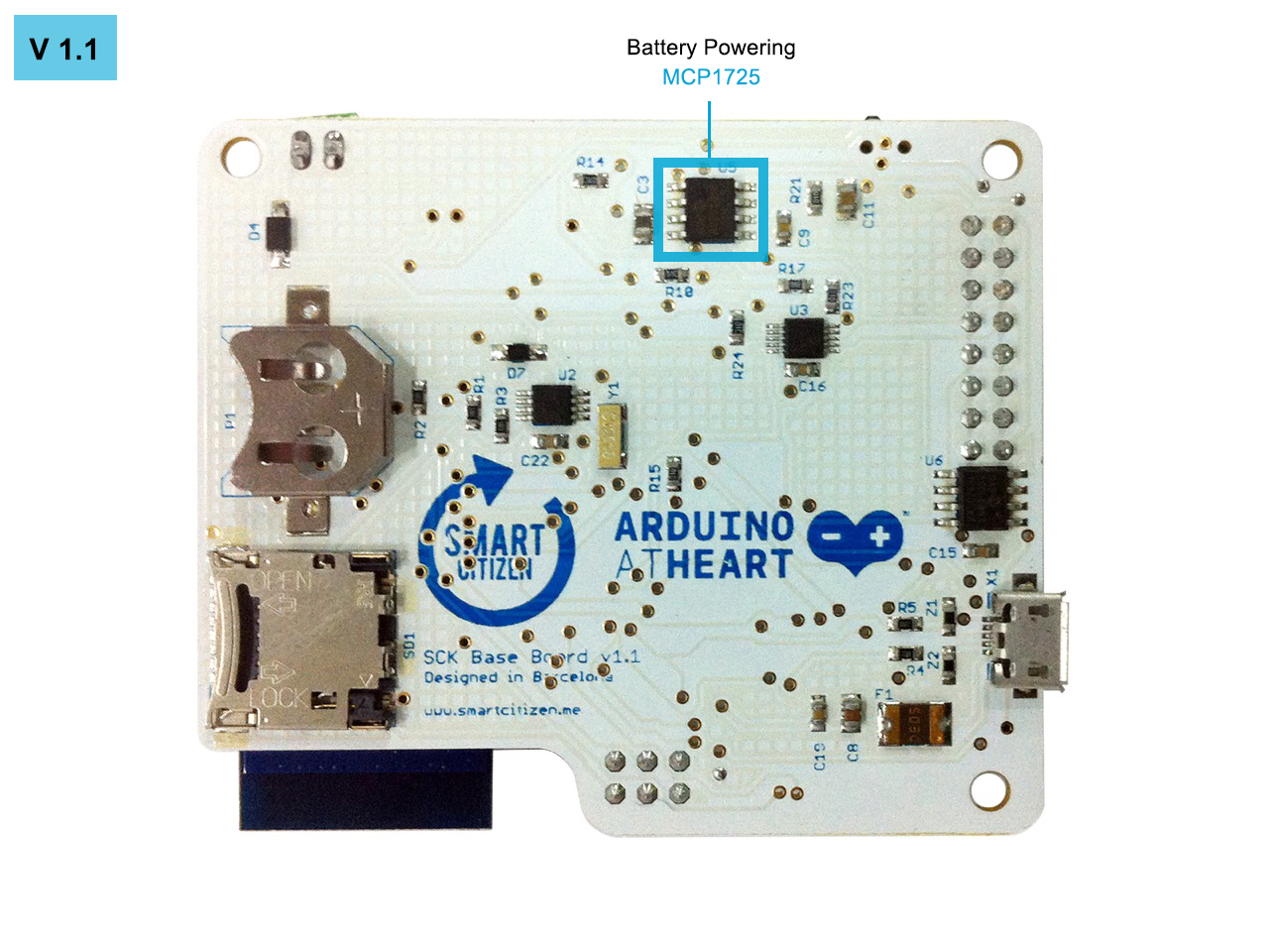
In 1.1 version, to make things simpler, the voltage of entire SCK was unified to 3.3V. The responsible to regulate the voltage from 3.7v to 3.3v is the MCP1725 IC.
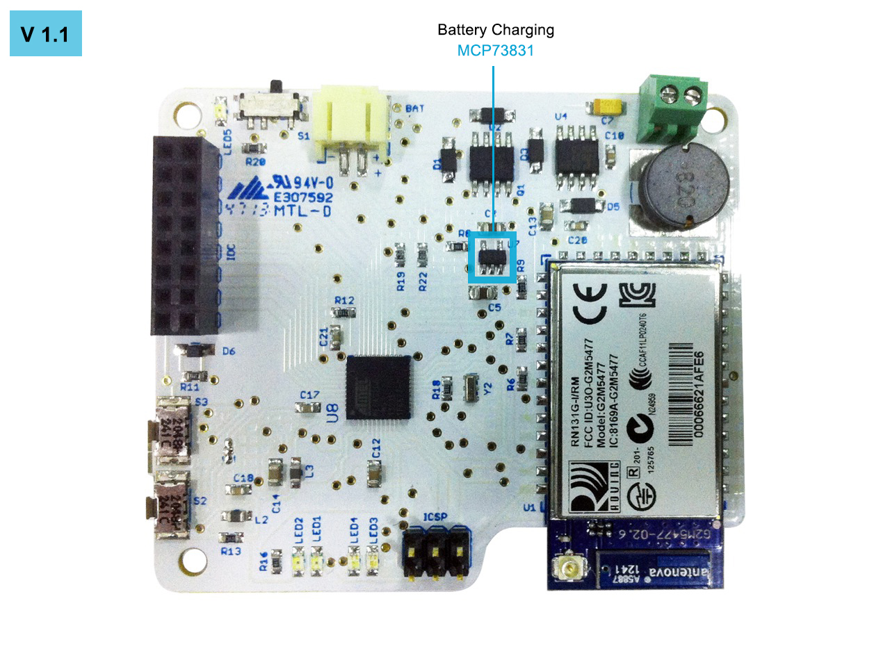
BATTERY CHARGING
For charging the battery there are two ways, USB or solar panel. To carry out the charging we are using MCP73831 IC.
For charging the battery in 1.0 version the solar panel have to be 12v and 500mA. In 1.1 version, the solar panel can be more versatile in terms of amperage.

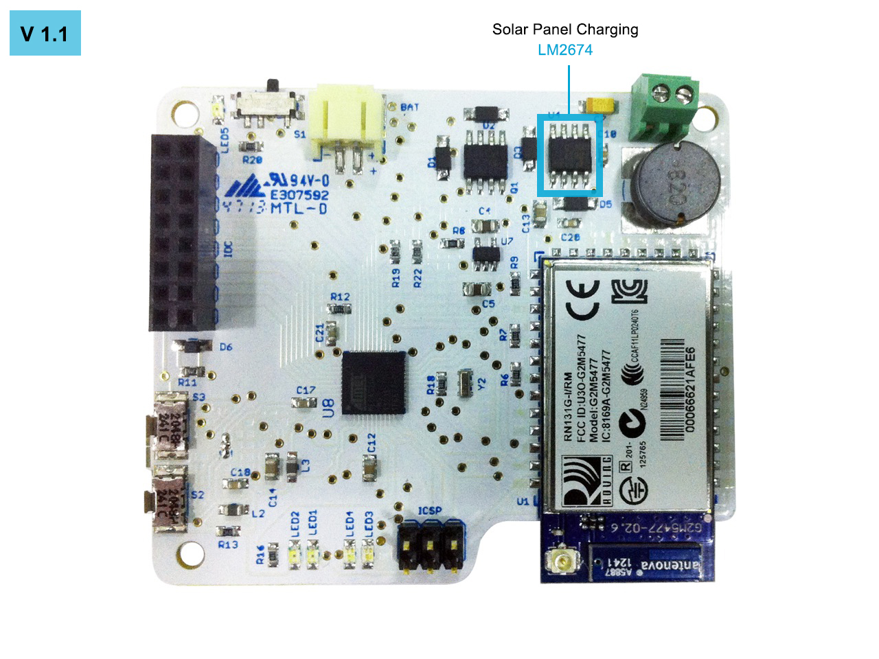
SOLAR PANEL CHARGING
Depending on the sunlight conditions the solar panel produces up to 12v, we have to reduce the voltage to 5v to feed up the Vin of the MCP73831 charger IC.
To carry out this task we are using the LM2674 IC, a very efficient IC, with a rate of 91% of performance.

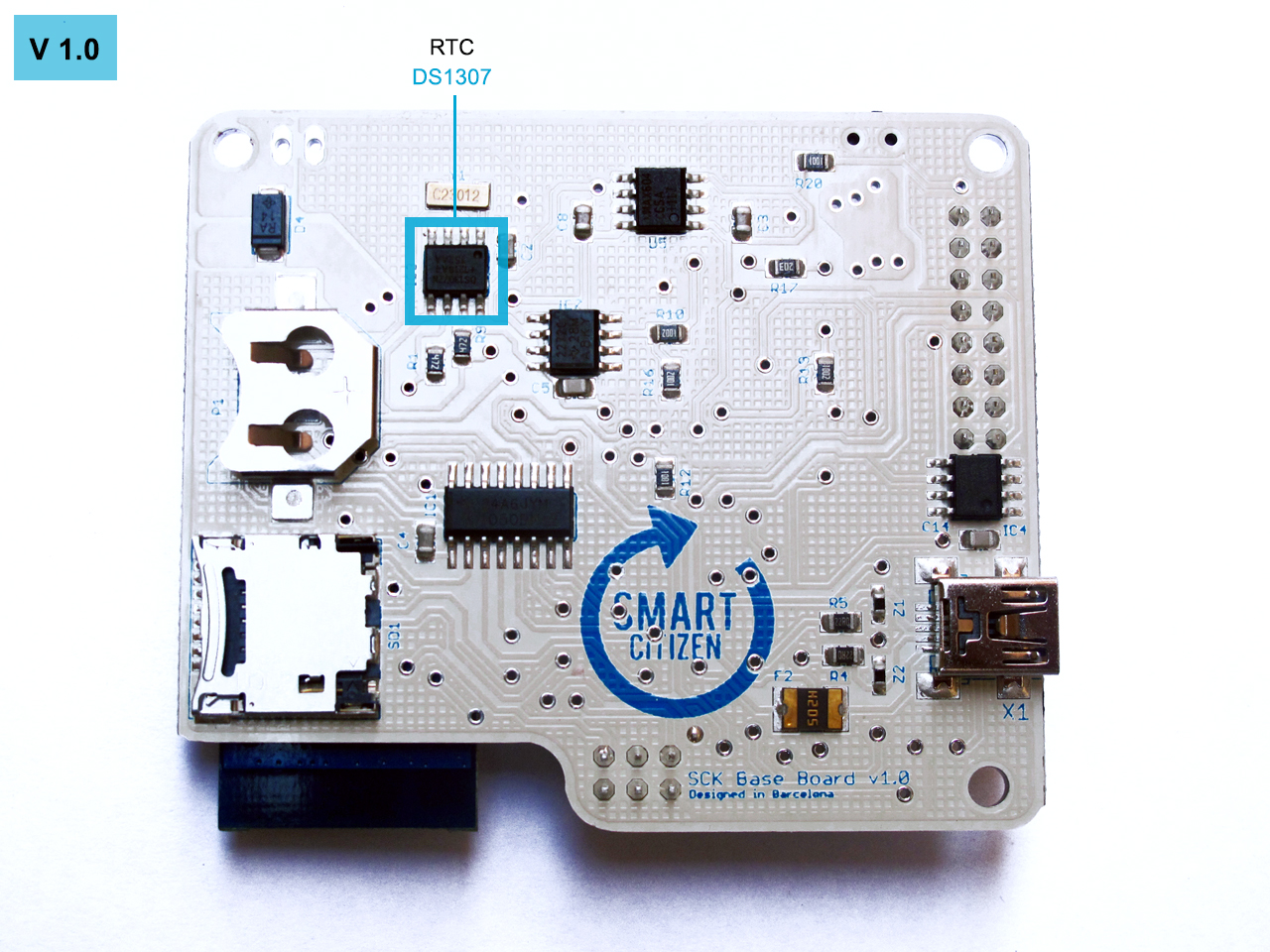
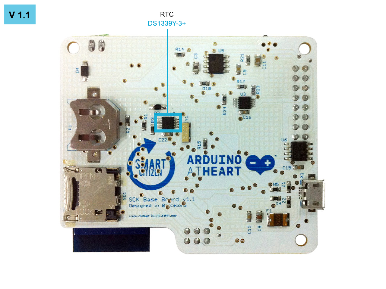
RTC (REAL TIME CLOCK)
The SCK has a real time clock for keeping track of time when the kit is offline. For this task we chose the DS1307 IC for the 1.0 version and the DS1339Y-3+ IC for the 1.1 version. Different IC due to the different voltages, 5V for the 1.0 version and 3.3V for the 1.1 version.
DS1307 datasheet
DS1339Y-3+ datasheet
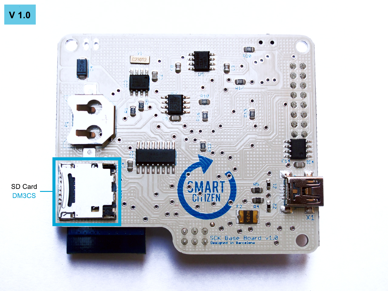
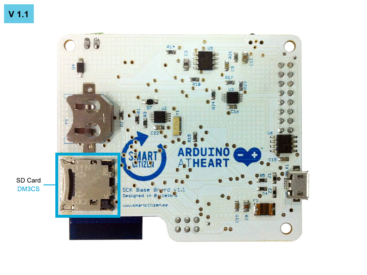
SD CARD READER
The SD card is used to store the data captured by the sensors when the kit is offline. When the kit gets connected, the data will be reeded from the SD card and uploaded to the platform.
To hold the SD card we are using the DM3CS holder. The SD card is powered at 3.3V and communicates with the CPU through SPI protocol.
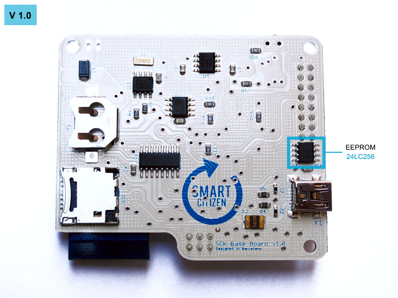
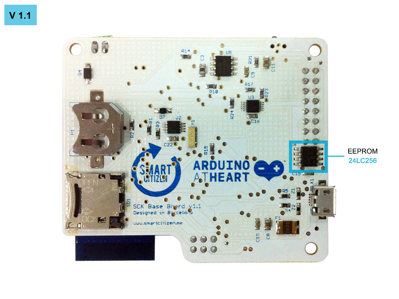
EEPROM MEMORY
For the users that don’t have a SD card we’ve added an EEPROM memory to store the data when the SCK is offline. We chose the 24LC256 IC that can store 32kBytes, it communicates with the CPU through I2C protocol.
MAIN BOARD BASIC SENSORS
The main board has some basic sensors:
- Measurement of the battery level
- Measurement of the solar panel level
- Measurement of the wireless networks detected
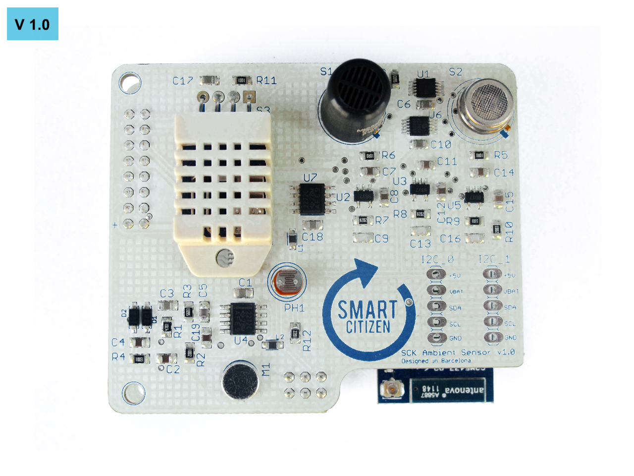
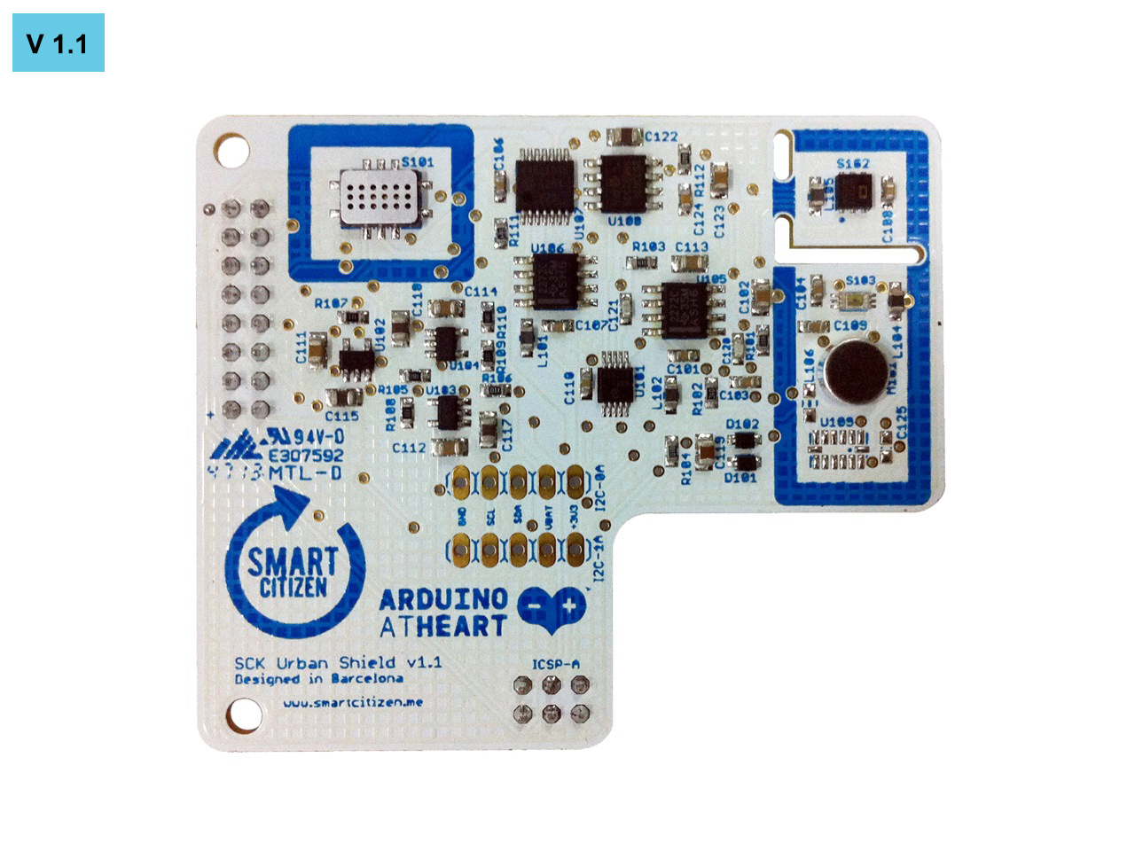
SENSOR BOARD
The sensor board contains the necessary sensors for measuring all the other parameters. This means NO2 and CO gases, sunlight, noise pollution, temperature, humidity. Also, the sensor board has an I2C bus, this allows to expand the SCK to other kind of sensors.
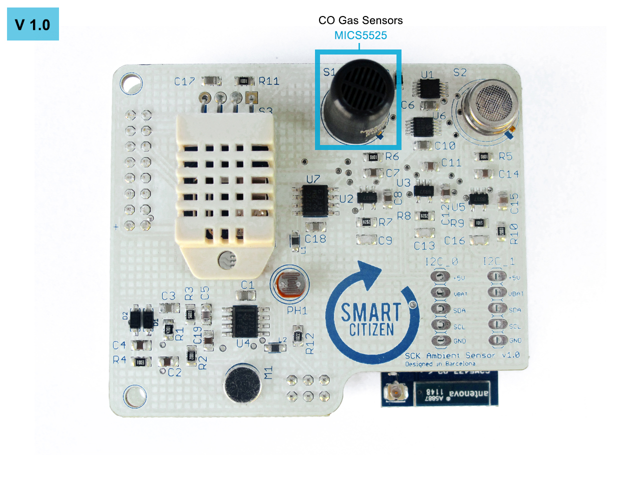
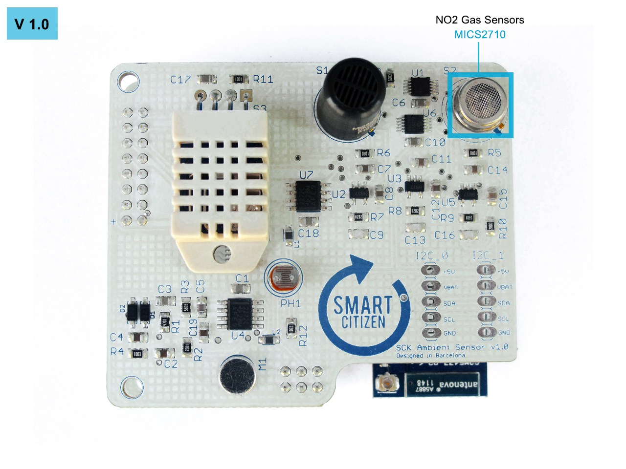
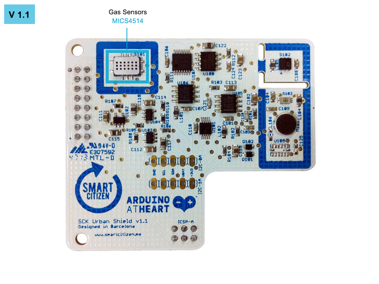
NO2 AND CO SENSORS
To measure these two gases we chose e2v sensors. In particular, metal oxide sensors MICS5525 and MICS2710, for version 1.0. And MICS4514, for version 1.1, that contains both sensors in one.
Metal oxide sensors are based on oxide semiconductors. Their electrical conductivity is modulated due to the reaction between the semiconductor and the gases in the atmosphere.
MICS5525 datasheet
MICS2710 datasheet
MICS4514 datasheet
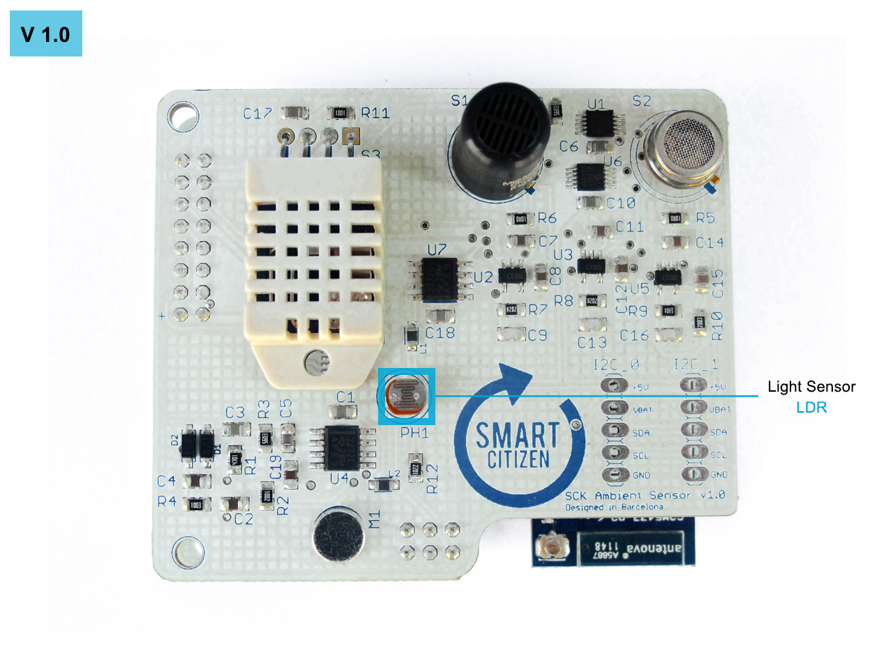
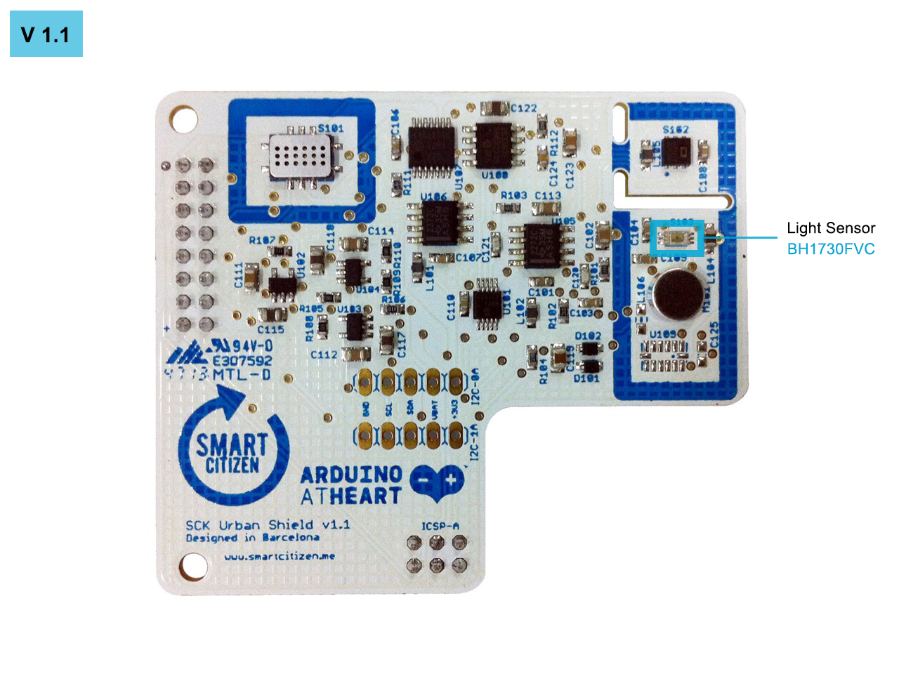
LIGHT SENSOR
The light sensor is a basic element to know the light pollution. In version 1.0, was used a LDR (light-dependent resistor) whose voltage varies depending on the light conditions.
For version 1.1, was used a photodiode BH1730FVC. This sensor contains an I2C bus that gives us directly the amount of lux of ambient and infrared light.
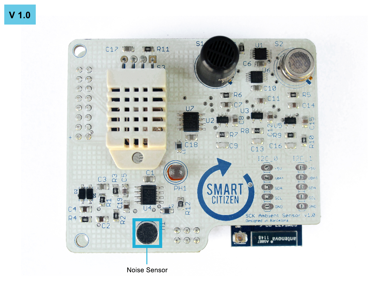
NOISE SENSOR
The noise sensor is based on an electret microphone. For the version 1.0 WM-61A was used as the microphone, the captured audio signal is passed through an operational amplifier configured as band pass filter.
For the version 1.1 POM-3044P-R was used.

WM-61A datasheet
POM-3044P-R datasheet
TEMPERATURE AND HUMIDITY SENSOR
To measure temperature and humidity a module that integrates both sensors was used.
For version 1.0 the RHT22 was used, it has one wire digital interface.
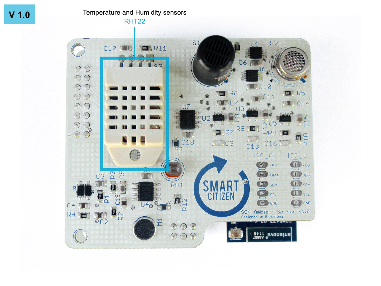
For version 1.1 the SHT21 was used, it has I2C protocol and faster response between measures than the RHT22.
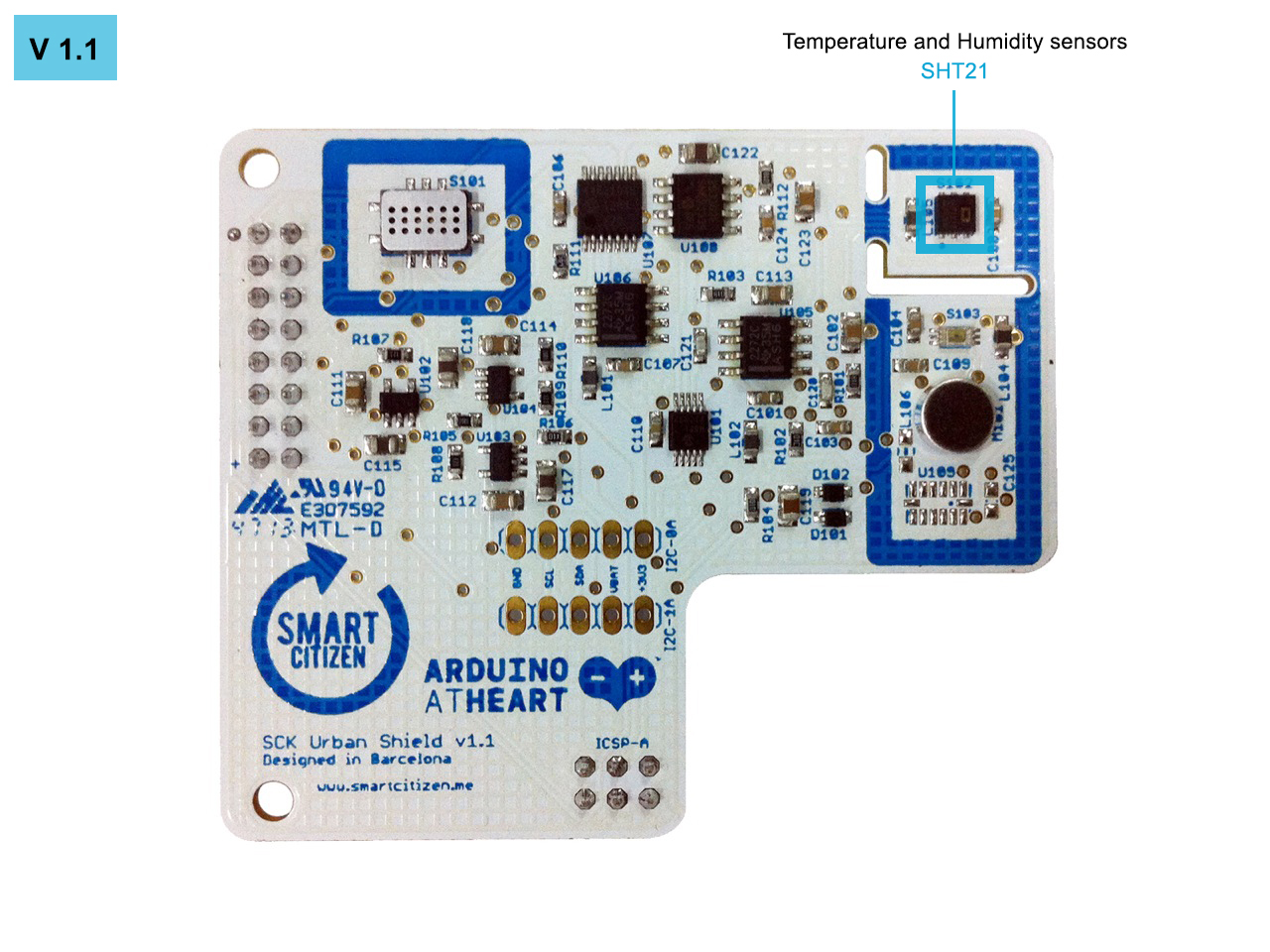
RHT22 datasheet
SHT21 datasheet
3 AXIS ACCELEROMETER
In version 1.0 we detected that some measures vary depending on the orientation of the SCK.
That's why in version 1.1 we added the ADXL345 accelerometer to detect the position and to compensate the measures depending on the orientation of the SCK. This accelerometer communicates via I2C protocol with the kit.

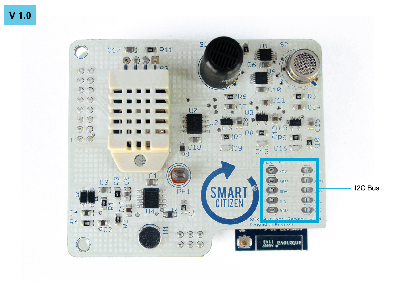
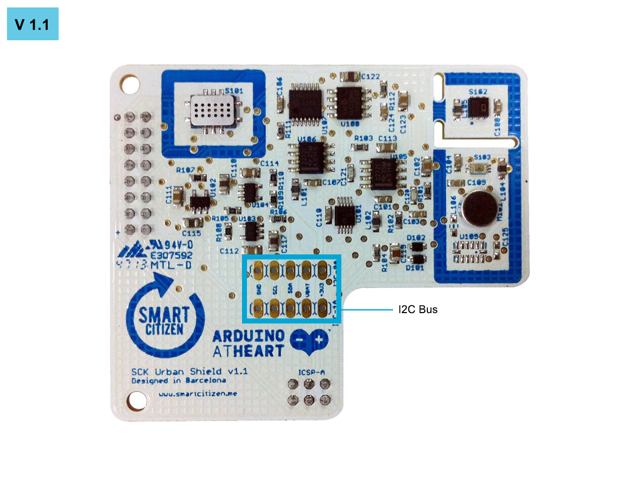
I2C EXPANSION BUS
Due to the ease of the I2C protocol. We’ve included and I2C bus to provide to the community the opportunity of expanding the SCK.
Detailed specifications
| Smart Smart Citizen Kit | SCK 1.0 (Goteo Board) | SCK 1.1 (Kickstarter Board) | SCK 1.5 (Upcoming!) |
|---|---|---|---|
| Data Board | |||
| MCU | ATMEGA32U4 | ATMEGA32U4 | SAMD21 |
| Clock | 16Mhz | 8Mhz | 32Mhz |
| WiFi | Microchip RN-131 802.11 b/g | Microchip RN-131 802.11 b/g | Espressif ESP8266-12E |
| Firmware | Repository | Repository | Repository |
| Design files | v1.01 | v1.1 | v1.5 |
| Ambient Board | |||
| Light | PVD-P8001 | BH1730FVC | BH1730FVC |
| Type | LDR Analog Light Sensor | Digital Ambient Light Sensor | Digital Ambient Light Sensor |
| Units | % | Lux | Lux |
| Datasheet | PDV-P8001.pdf | BH-1730FCV.pdf | BH-1730FCV.pdf |
| Performance | 0.008 - 65535 lx (± 15%) ** | 0.008 - 65535 lx (± 15%) ** | |
| Firmware | SCKAmbient::getLight(); |
SCKAmbient::getLight(): |
Under development |
| Temp | DHT22 | HPP828E031 (SHT21) | SHT21 |
| Type | Digital Temperature and Relative Humidity Sensor | Digital Temperature and Relative Humidity Sensor | Digital Temperature and Relative Humidity Sensor |
| Units | ºC | ºC | ºC |
| Datasheet | DHT22.pdf | HTU-21D.pdf | SHT-21.pdf |
| Firmware | SCKAmbient::getDHT22(); SCKAmbient::getHumidity(); |
SCKAmbient::getSHT21(); SCKAmbient::getTemperature(); |
Under development |
| Performance | Linearity R²>0.94 * | Under tests | |
| Humidity | DHT22 | HPP828E031 (SHT21) | SHT21 |
| Type | Digital Temperature and Relative Humidity Sensor | Digital Temperature and Relative Humidity Sensor | Digital Temperature and Relative Humidity Sensor |
| Units | % Rel | % Rel | % Rel |
| Datasheet | DHT22.pdf | HTU-21D.pdf | SHT21.pdf |
| Firmware | SCKAmbient::getDHT22(); SCKAmbient::getHumidity(); |
SCKAmbient::getSHT21(); SCKAmbient::getHumidity(); |
Under development |
| Performance | Linearity R²>0.97 * | Under tests | |
| NO²ise | POM-3044P-R | POM-3044P-R | SPU0414HR5H |
| Type | Electret microphone with envelop follower sound pressure sensor | Electret microphone with envelop follower sound pressure sensor | New MEMS microphone with envelop follower sound pressure sensor |
| Units | dB | dB | dB |
| Datasheet | POM-3044P-R.pdf | POM-3044P-R.pdf | SPU0414HR5H.pdf |
| Firmware | SCKAmbient::getNO²ise(); |
SCKAmbient::getNO²ise(); |
Under development |
| *Performance | Range 50dB - 110dB (± 15%) ** | Under tests | |
| CO | MICS-5525 | MiCS-4514 | MiCS-4514 |
| Type | MOS CO gas sensor | MOS CO and NO² gas sensor | MOS CO and NO² gas sensor |
| Units | kOhm (ppm) | kOhm (ppm) | kOhm (ppm) |
| Datasheet | MICS-5525_CO.pdf | MiCS-4514_CO_NO2.pdf | MiCS-4514_CO_NO2.pdf |
| Firmware | SCKAmbient::getMICS(); |
SCKAmbient::getMICS(); |
Under development |
| Performance | Linearity 0.45 < R² < 0.82 * | Under tests | |
| NO²2 | MICS-2710 | MiCS-4514 | MiCS-4514 |
| Type | MOS NO² gas sensor | MOS CO and NO² gas sensor | MOS CO and NO² gas sensor |
| Units | kOhm (ppm) | kOhm (ppm) | kOhm (ppm) |
| Datasheet | MICS-2710_NO2.pdf | MiCS-4514_CO_NO2.pdf | MiCS-4514_CO_NO2.pdf |
| Firmware | SCKAmbient::getMICS(); |
SCKAmbient::getMICS(); |
Under development |
| Performance | Linearity R²<0.0 * | Under tests |
** * ** South Coast AQMD The correlation coefficient (R²) is a statistical parameter indicating how well the performance of each sensor compares to that of a Federal Reference or Federal Equivalent Method (FRM and FEM, respectively) instrument. An R² approaching the value of 1 reflects a near perfect agreement, whereas a value of 0 indicates a complete lack of correlation
** * ** Internal Smart Citizen Team WIP Evaluation Tests
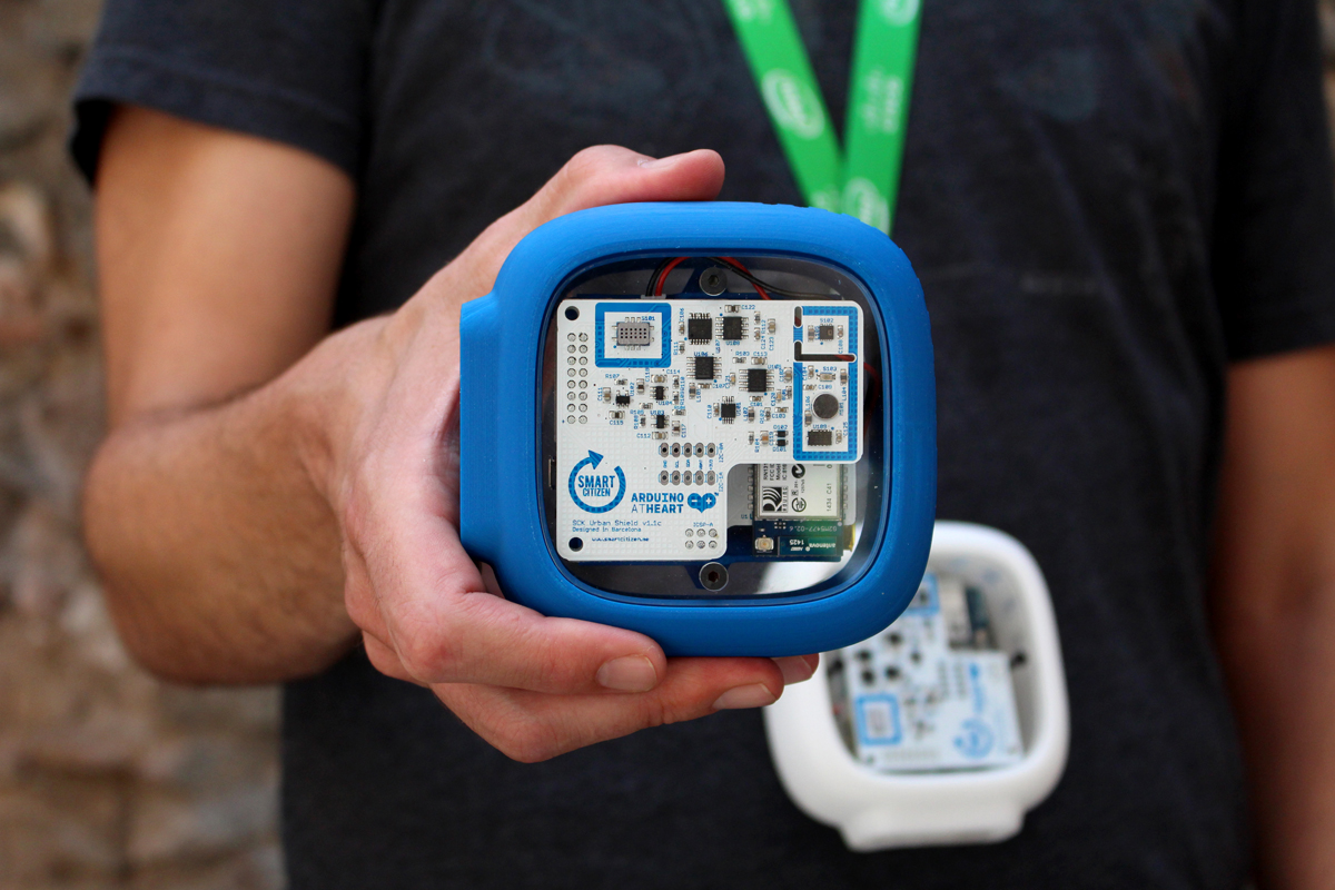
Enclosures
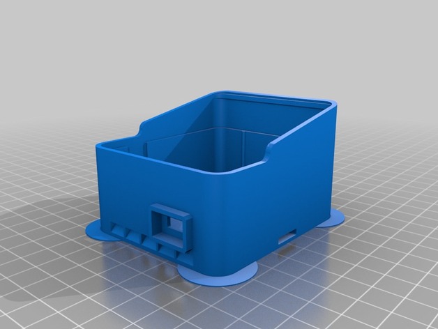
We have designed a laser cut cover for an acrylic material and a 3D-Printed enclosure to better safeguard the hardware, particularly for outdoor applications.
You can download the files through this links.
Smart Citizen Enclosure 1.0
Smart Citizen Enclosure 1.1
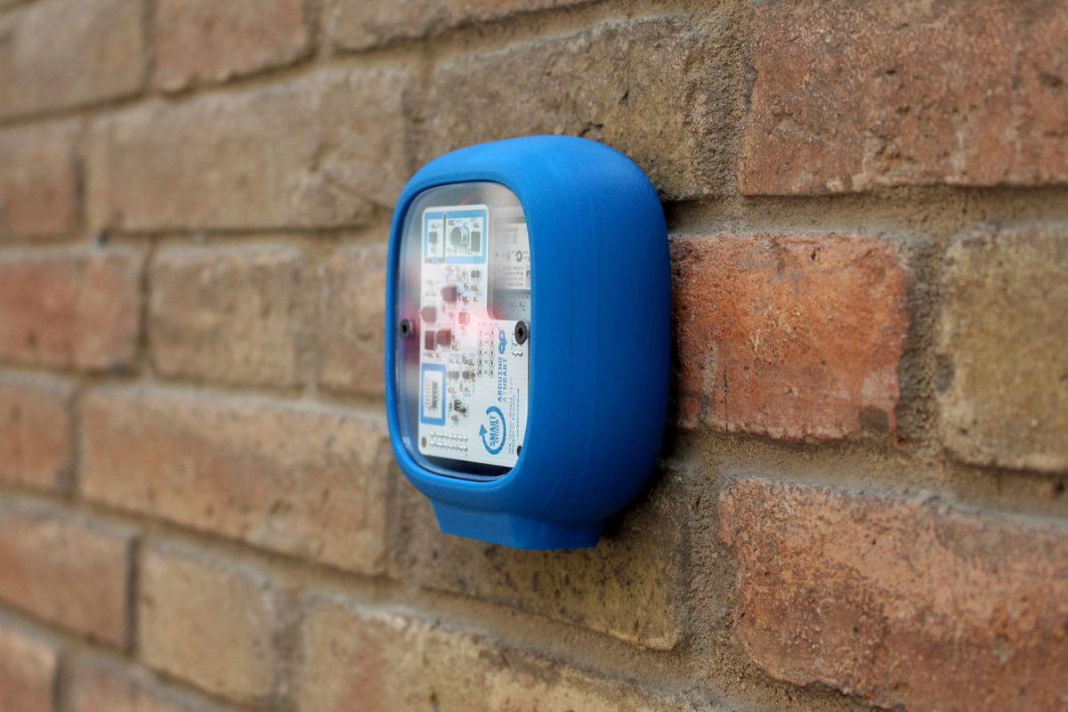
Also, we are working in new cases that will be available soon.
Smart Citizen Enclosure Assembly Instructions
Acrylic cases
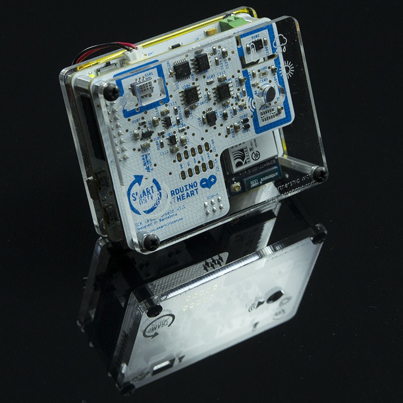
This case has been designed to protect the electronics on the circuit boards and allows for mount the SCK's hardware on walls and other surfaces without much trouble. Particularly for indoor applications.