Deploying the Smart Citizen Station
This guide will summarise how to install the Smart Citizen Station and set it all up for successful readings.
Hardware
The Stations should come assembled and ready to use. It consists of various parts:
- Enclosure and mounting system
- Sensors module
- Power supply
This is how the smaller version looks like:
Physical measurements
The big Station measurements are shown in the image below:
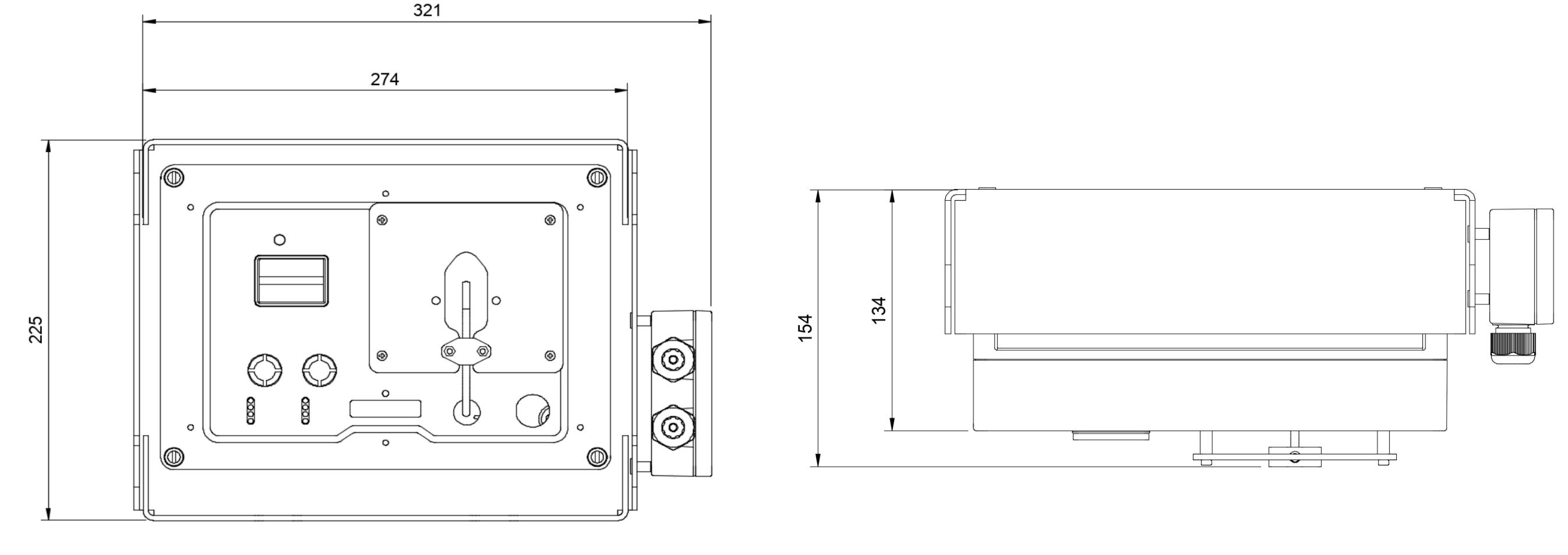
- Dimensions with cover (length, height, depth) (approx.): 340mm x 160mm x 230 mm
- Dimensions without cover (length, height, depth) (approx): 260mm x 120mm x 180mm
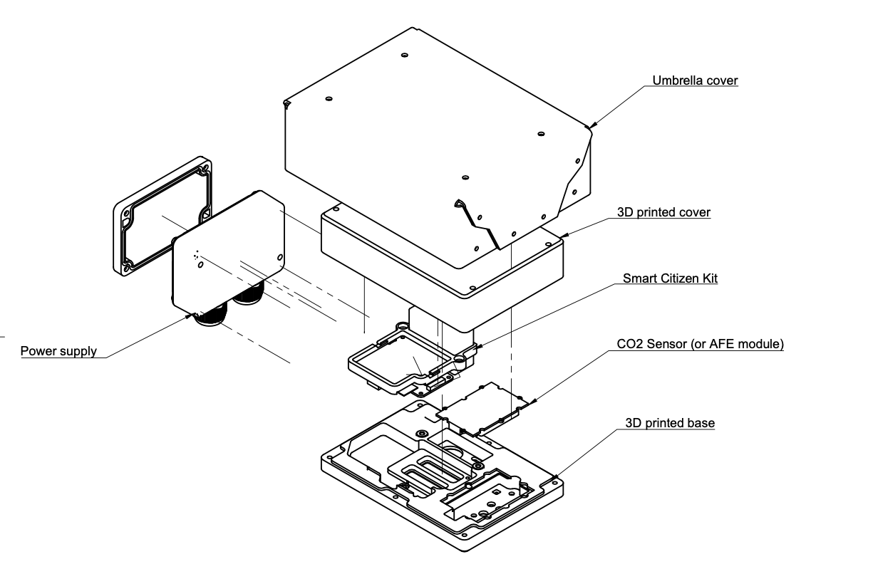
The small Station measurements are shown in the image below:
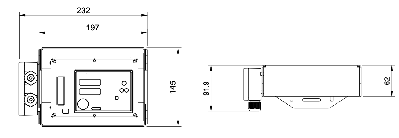
- Dimensions with cover (length, height, depth) (approx.): 232mm x 92mm x 145 mm
- Dimensions without cover (length, height, depth) (approx): 150mm x 105 x 45 mm
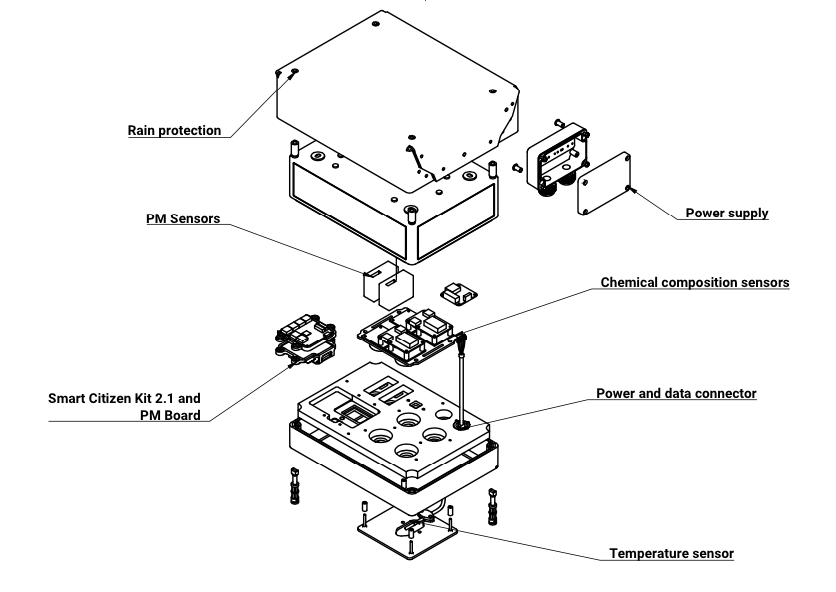
Enclosure and mounting system
The enclosure and mounting system is very similar for both units:
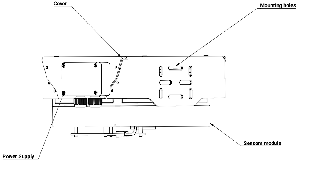
The enclosure holds the sensors in place and protects them against weather. A rain and sun radiation cover for protection made out of white sandwich panel or dibond. This element carries out the structural support of the station and protects the unit against rain, wind or heat.

The sensors module which contains the electronics and sensors, is attached to the cover and can be removed without having to uninstall the rain cover.
Finally, The power supply, is a separated from the module, so that intervention in the sensors' area can be performed safely with a tangible desconection of the mains power.
Flexible attachment
This mounting is thought to work on a lampost, fence or wall. We recommend a somewhat flexible join (i.e. zip-ties) in case of windy locations
Power supply details
Refer to the Power supply section and the guide on it's installation for more details.
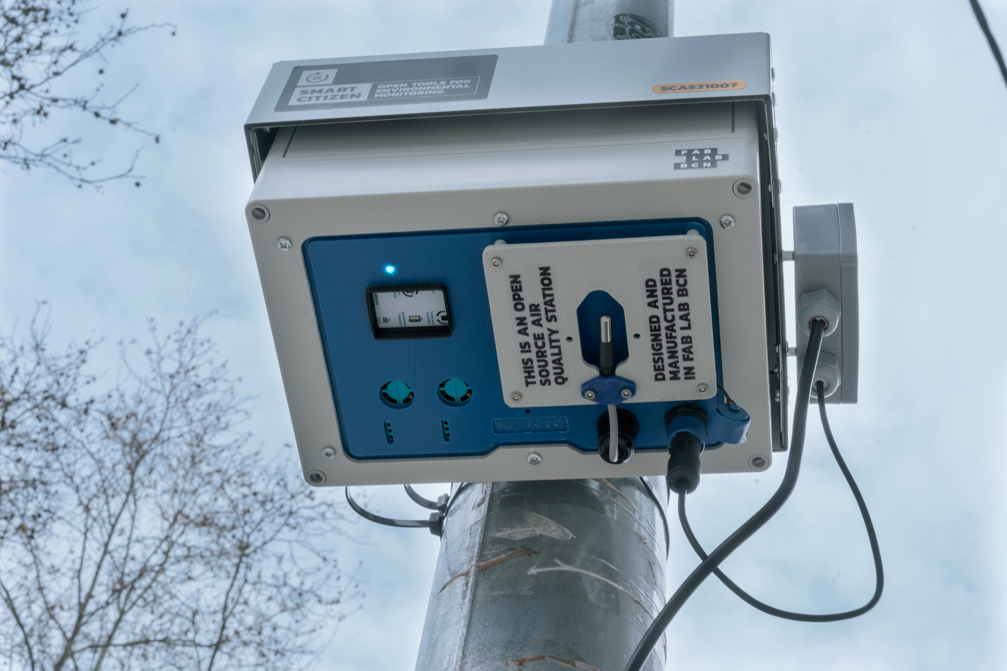
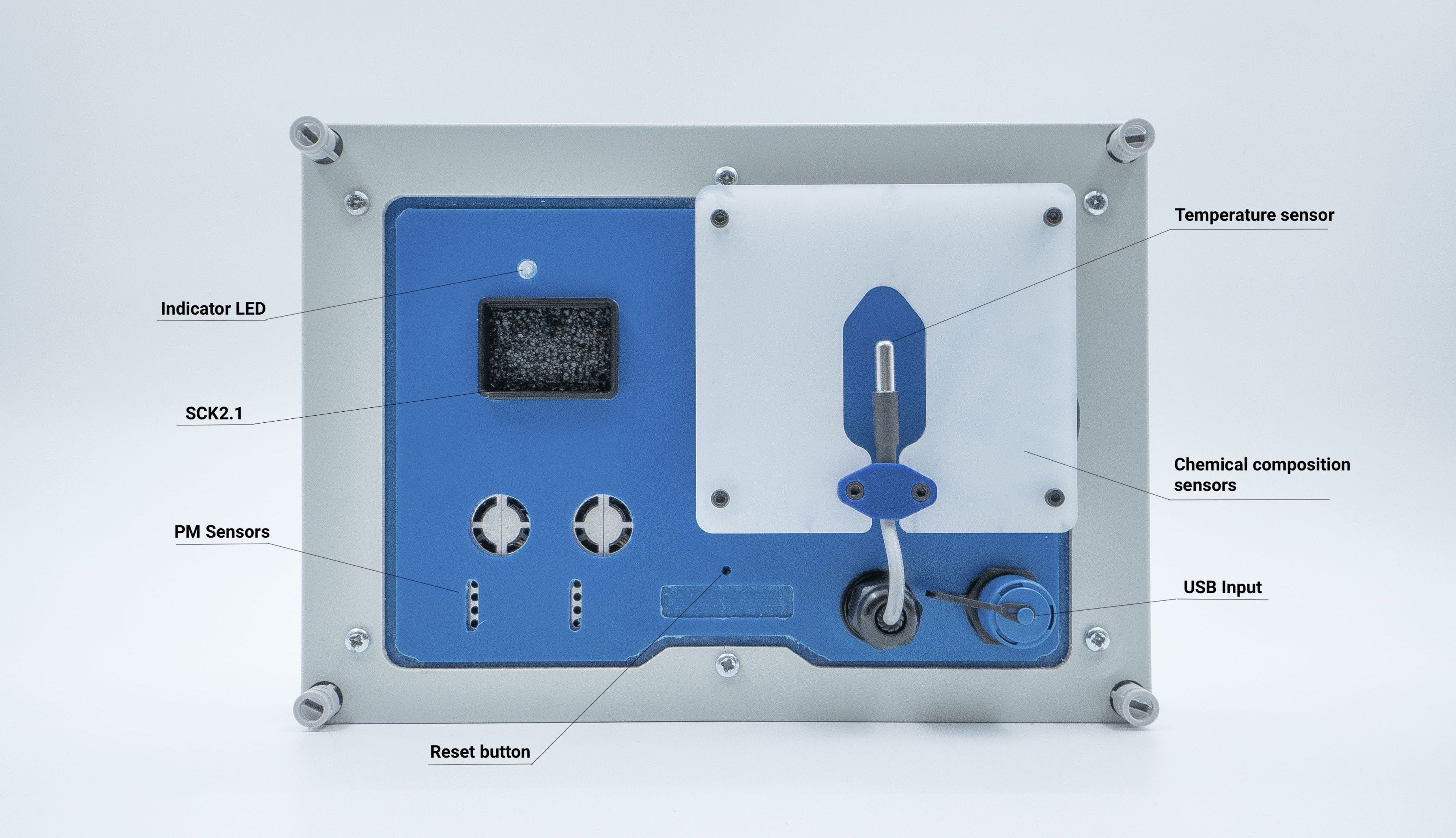
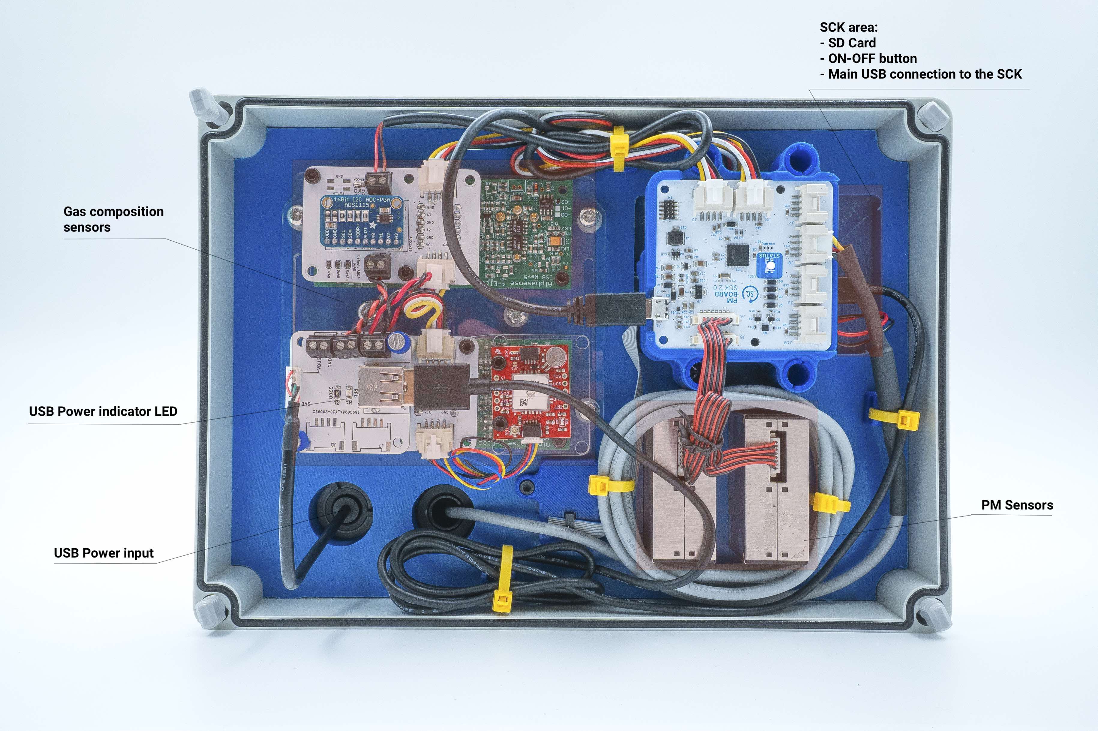
Sensors module
The sensors module is the area where all the action takes place. This is the bottom view:
An this is the inside one (will change with further development):
The small Station looks like this:
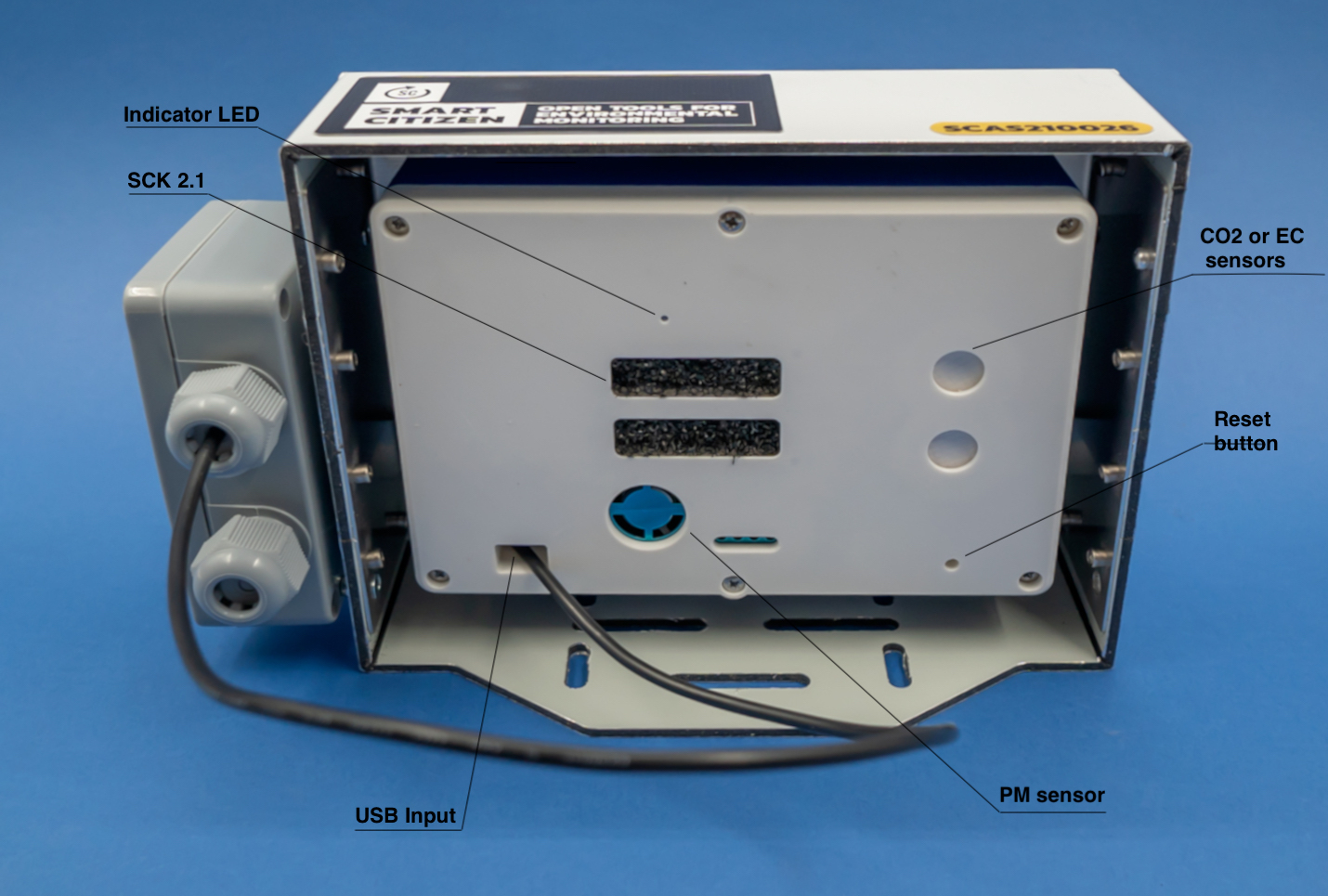
The Station is powered through it's USB input. It can be reset by either:
- disconnecting the power to the mains
- introducing a thin screw driver or pen through the RESET button hole indicated above
Power USB
We do not recommend to use any other cable than the supplied one in outdoor conditions.
Power supply
The Smart Citizen Station uses the Smart Citizen Power Supply for power. The input of the station is the connector shown in the image below.

Inside the station, power is distributed accross the different units. Data and power goes through the input, in order to connect to the Data Board and be able to use the Shell. All voltage levels inside the station are below 5V.
Using the power supply
For more information about how to handle the Smart Citizen Power Supply, have a look at this guide for safety instructions.
Installation

Follow the steps below for making sure everything is working fine before setting it up in an outdoor spot.
-
First, power the unit with the USB provided. The unit can be powered with a normal USB charger first for configuration, or with a laptop as well. If you have a laptop at hand it's going to be handy for step 3.
-
The indicator LED should turn on. It will first be GREEN, WHITE (may take a while) and then RED or BLUE, depending on the configuration of the Station. You can see more information on the LED status here
-
If you have a laptop available, it is recommended to check with the Shell and request the sensors:
sensorAfter this, a list of all the enabled sensors should appear. You can configure the recording interval as well, in case you need less or more data. If all is working fine, you can now proceed to installation of the unit in an outdoor spot.
This is a list of all the possible sensors in the Station (seen from the hardware side), the actual sensor list will depend on your version:
Temperature
Humidity
Battery
Light
Noise dBA
Barometric pressure
VOC Gas CCS811
eCO2 Gas CCS811
PM board Dallas Temperature
ADS1x15 ADC 0x48 Ch0
ADS1x15 ADC 0x48 Ch1
ADS1x15 ADC 0x48 Ch2
ADS1x15 ADC 0x48 Ch3
ADS1x15 ADC 0x49 Ch0
ADS1x15 ADC 0x49 Ch1
ADS1x15 ADC 0x49 Ch2
ADS1x15 ADC 0x49 Ch3
ADS1x15 ADC 0x4A Ch0
ADS1x15 ADC 0x4A Ch1
ADS1x15 ADC 0x4A Ch2
ADS1x15 ADC 0x4A Ch3
ADS1x15 ADC 0x4B Ch0
ADS1x15 ADC 0x4B Ch1
ADS1x15 ADC 0x4B Ch2
ADS1x15 ADC 0x4B Ch3
Ext PM_A 1.0
Ext PM_A 2.5
Ext PM_A 10.0
Ext PM_B 1.0
Ext PM_B 2.5
Ext PM_B 10.0
Check the meaning of the sensor channels
This a complete list of sensors. Have a look at it to get a full description and location of each of them.
This is an example of the sensor list in a normal 4-electrochemical sensors Station (with some additional comments for clarity):
```
-----------------------
Sensors in Urban Board
-----------------------
Temperature
Humidity
Battery
Light
Noise dBA
Barometric pressure
VOC Gas CCS811
eCO2 Gas CCS811
-----------------------
Sensors in Auxliary Bus
-----------------------
# External temperature sensor
PM board Dallas Temperature
# Electrochemical sensors voltages
ADS1x15 ADC 0x48 Ch0
ADS1x15 ADC 0x48 Ch1
ADS1x15 ADC 0x48 Ch2
ADS1x15 ADC 0x48 Ch3
ADS1x15 ADC 0x4A Ch0
ADS1x15 ADC 0x4A Ch1
ADS1x15 ADC 0x4A Ch2
ADS1x15 ADC 0x4A Ch3
# Particulate matter sensors
Ext PM_A 1.0
Ext PM_A 2.5
Ext PM_A 10.0
Ext PM_B 1.0
Ext PM_B 2.5
Ext PM_B 10.0
```
Sensor readings
Sensor readings for the Electrochemical sensors are sent in raw and later on processed. Each electrochemical sensor has two outputs read by one of the ADCs so, for 4 electrochemical sensors, we need at least 8 channels.
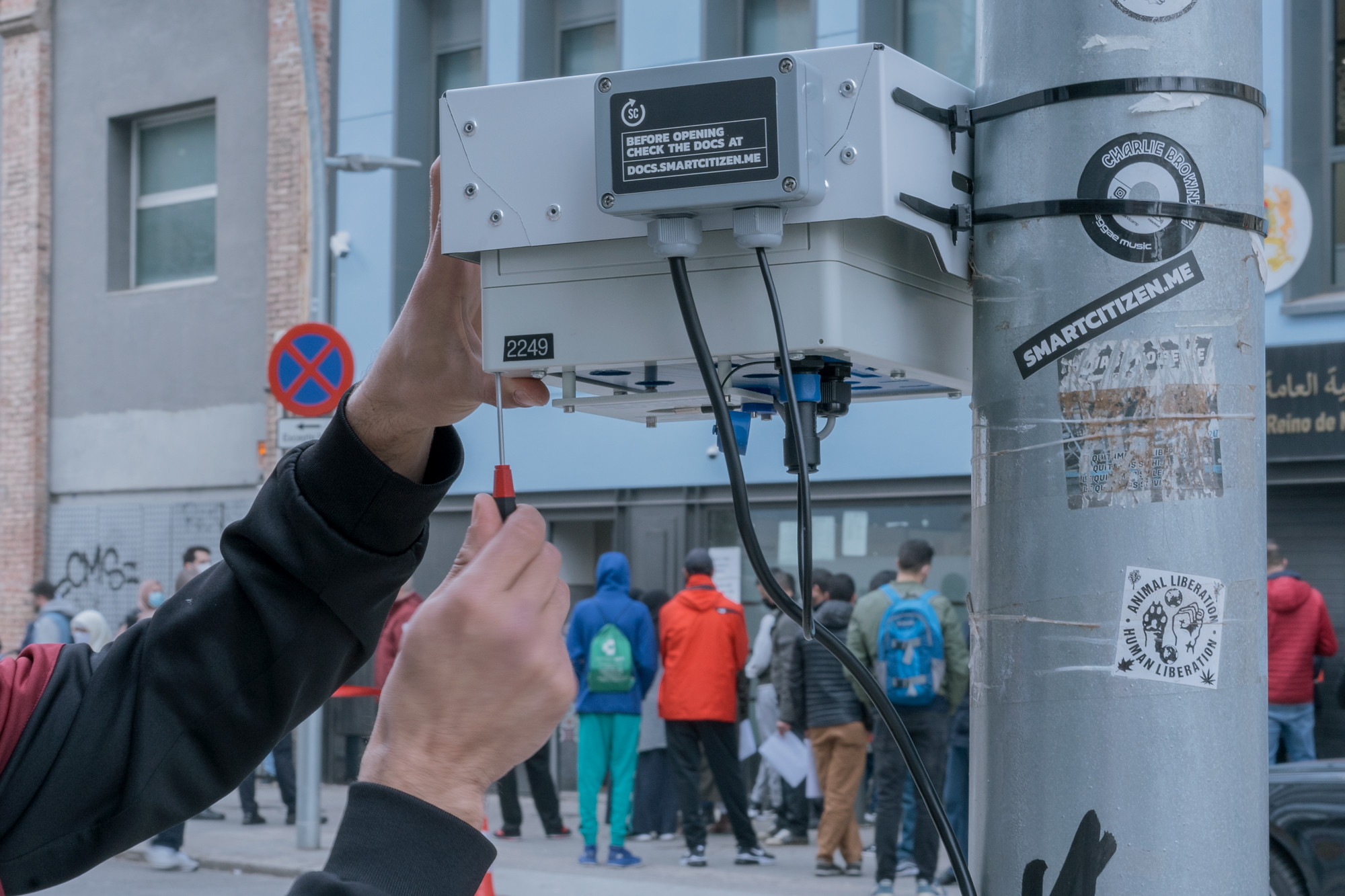
Physical installation
The enclosure can be installed using the mounting holes seen below. There is sufficient space to pass zip ties. If you want to use drills, we recommend at least 6mm screws (or 8mm) and to dissasemble the plastic cover from the sandwich pannel for safer installation.
Below are some general guidelines for the installation of the device:
- Avoid areas with moist accumulation when possible
- Avoid temperature and humidity transients
- Avoid covering the sensors in front of the sensors, specially the PM sensor
- Avoid covering the microphone and particles to go in the microphone port
- Avoid direct flow towards the sensors. If exposed under flow conditions, have the flow go parallel to the sensors' surface
- Despite the umbrella cover, sun radiation and transients are better to be avoided
- A good height for installing the sensors is somewhere between 2-3m, but it all depends on the case study and available support structures.
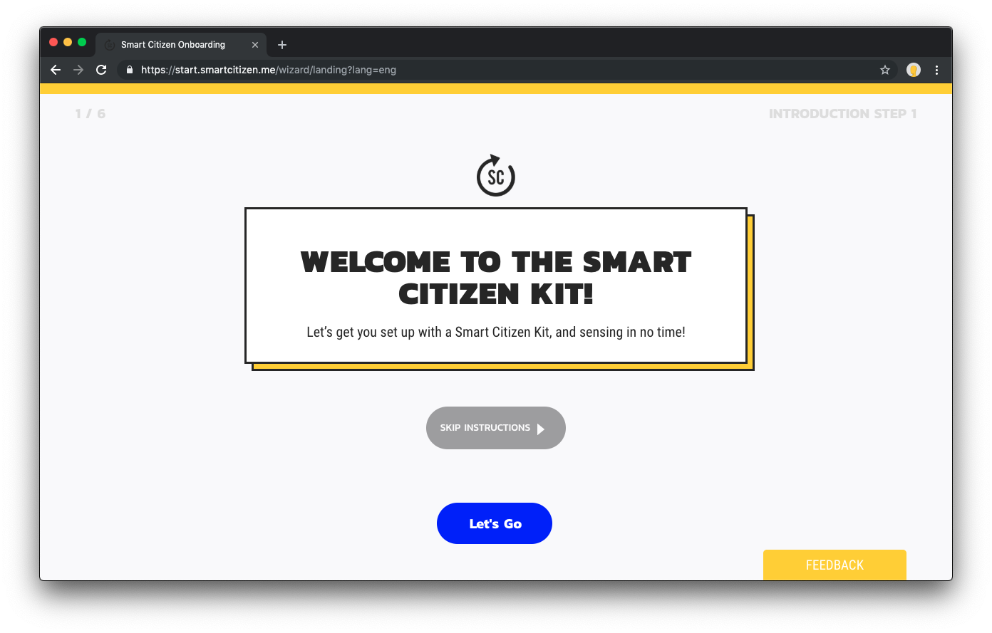
Configuration

The process to register the Smart Citizen Station and send data to the platform is the same as the one from the Smart Citizen Kit (start.smartcitizen.me):
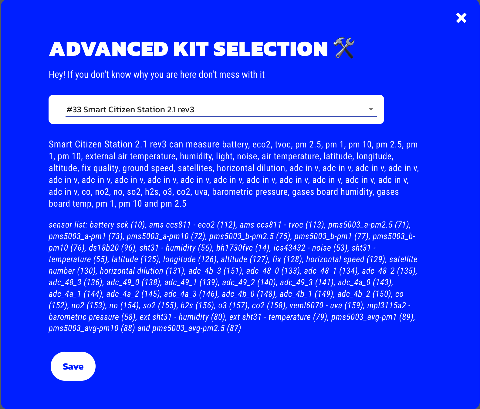
Only, make sure to select the appropiate Kit (#33 Smart Citizen Station 2.1 rev3) in the Advanced Selection field:
Advanced tip
If you are familiar with Shell commands, or you use Arduino IDE to interact with the Station, you can use this Shell Guide, and connect to the device. Then write down the configuration that you get when typing config:
SCK > config
Mode: network
Publish interval: 180
Reading interval: 60
Wifi credentials: WIFI-SSID - WIFIPASS
Token: 123456
Mac address:  XX:XX:XX:XX:XX
Also, if you are using the phone, you can turn the unit to SETUP mode again, using the ON-OFF button (the indication LED should shine in RED) and from there connect to the Station and get it's information:
Handling calibration data
Some components of the Station have individual calibrations such as the Alphasense Electrochemical Sensors. For this reason, it's necessary to store the physical ID (hardware ID) of the Station alonside to the virtual device in the Smart Citizen Platform. The harwdware ID should normally be in a sticker to the enclosure both inside and outside and looks like this:
SCAS2100XX
This number is important to relate to the actual calibration values of the sensors, stored in the data repository. In order to postprocess the data and calculate pollutants, make sure that the Hardware ID is safely stored in the platform's device, by posting this data to postprocessing_info field of the device. You can follow these instructions to store the postprocessing_info of your device.
All the data is sent in raw to the Smart Citizen Platform and it's then processed outside of the sensors themselves. Both raw, and processed data are kept on the platform and can be accessed at any time. Data can be published to other APIs or to Zenodo as well, in case of research projects that seek contribution to Open Science Datasets.
More on the processing of the data
Check this guide to learn more about how to postprocess the data of the sensors your own way.
Troubleshooting
The first step in case anything goes wrong, is to reset the unit by pressing the RESET button. If this doesn't work, make sure that your problem is not already listed in the FAQs, and if not, contact us for more support.
